A Self-Compensation Approach for Maintaining the Chromaticity Coordinates of Phosphor Converted LEDs Upon Temperature Variations
Solid-state light sources for general illumination applications are currently becoming more and more popular. Maintaining chromaticity coordinates over temperature is a challenge. Wolfgang Nemitz, Franz P. Wenzl, Susanne Schweitzer, Christian Sommer, Paul Hartmann from the Institute for Surface Technologies and Photonics at Joanneum Research, and Paul Fulmek and Johann Nicolics from the Institute of Sensor & Actuator Systems of the Vienna University of Technology investigated this issue and propose a promising new solution.

The most common approach for white light generation relies on a combination of blue LED light and excited emission from one or more phosphor materials. This approach is still a big challenge when it comes to fulfilling the requirements for white light quality, for example, keeping the chromaticity coordinates of a single LED light source constant during operation and lifetime. Current approaches to solve this problem typically rely on a readjustment of the chromaticity coordinates by means of sensors and drivers technologies. This reduces the energy efficiency, increases the size and cost of the light sources, and decreases long- term reliability.
Recently, we suggested that it might be possible to compensate temperature induced impacts on the color temperature constancy, as they may occur for different operational conditions, to some extent without additional sensors and drivers: namely simply by using a sophisticated composition of the materials used in the color conversion element (CCE), which typically consists of the phosphor particles embedded in a silicone matrix. In fact, materials with appropriate optical properties can be combined in order to compensate opposite color shifts when, for example, the temperature in the device is increased and the quantum efficiency of the phosphor is reduced. One approach in this regard relies on the use of materials with suitable thermo-optic coefficients.
Introduction
Although the phenomenon of electroluminescence has been known for more than 100 years [1,2], it took until the early 1990s for efficient blue LEDs, which are the core elements for solid-state lighting (SSL), to become available. From that time on, a great amount of worldwide industrial and academic research activities resulted in rapid enhancement of both device performance and life time, which resulted in solid state lighting sources replacing traditional ones for more and more applications [3, 4]. Nonetheless, as noted, estimates are that SSL has only reached the halfway point in terms of lighting efficiency, which leaves a lot of challenges ahead. Not only in terms of energy efficiency, but also for color quality and control, as well as other advantages that remain largely untapped [5].
The color variation among individual LEDs should be in the order of a 2-step MacAdam ellipse [6] for white LEDs to be accepted for general lighting. There are several reasons why it is hard to meet this demand with today’s most common approach for white LEDs that relies on color conversion by a phosphor. This phosphor is part of the color conversion element (CCE) that typically consists of phosphor particles embedded in a silicone matrix. While this concept seems to be rather trivial, recent studies have shown that the performance of phosphor converted LEDs in terms of light output and white light quality also critically depends on the shape, composition and arrangement of such CCEs within the LED package [7 - 10].
Moreover, phosphors generally face the problem of decreasing luminescence intensity with increasing temperature. Thus, the contribution of the phosphor emission to the overall emission spectrum decreases with temperature, which severely affects the color temperature constancy of phosphor converted LEDs under operation, in particular when the driving current is varied. In a recent publication, based on optical simulations using a reference LED system consisting of an LED die and a conceptual simple CCE with a square shape and a flat surface, we have shown that a reduction of the quantum efficiency of the phosphor by about 6 % would result in a color deviation matching the outer limits of a MacAdam ellipse in step 2 [11]. For practical applications this value should be much smaller in order to give leeway to the other potential sources for color deviation that will add up to the final color shift.
Although recent progress in materials synthesis brought about much progress in new phosphors with lower temperature dependencies of luminescence quenching, it will be very difficult to maintain color variations within the above mentioned tolerance ranges, in particular since the temperatures within the CCE may become considerably high under operation [12 - 14]. Thus, it is insufficient to restrict strategies to diminish temperature induced color shifts simply to progress further in phosphor development. On the other hand, current approaches to solve this problem typically rely on a readjustment of the chromaticity coordinates by means of sensors and drivers technologies. This, however, reduces the energy efficiency, and increases the size and cost of the light sources, and decreases long-term reliability.
We recently presented an approach that, in combination with phosphors having a high thermal stability of their luminescence intensities, has the potential to alleviate temperature induced color shifts to a large extent [15]. This approach is based on the thermo-optic coefficients dn/dT of the materials constituting the CCE, in particular that of the phosphor and the silicone matrix. While silicones typically have a comparably large thermo-optic coefficient, phosphors likw Ce:YAG, have a much lower one. In addition, as typical for polymers, the thermo- optic coefficient of silicone is negative. This means the refractive index decreases with increasing temperature. Since the refractive index of the silicone matrix material is generally smaller than the one of the phosphors and due to its much larger thermo-optic coefficient, a reduction of the refractive index of silicone will enlarge the differences of the refractive indexes of the silicone and the phosphor with increasing temperature. This will therefore enhance light scattering that is the reason for a more yellowish emission in itself. On the other hand, also the luminescence intensity of the phosphors generally decreases with temperature, which in itself gives reason for a more bluish emission. Adjusting the thermo-optic coefficients of the CCE materials to the respective temperature dependent luminescence, loss of a phosphor can therefore be applied to counterbalance the corresponding color temperature shift due to the luminescence loss of the phosphor.
In the following we extend these previous studies and show how the use of a multilayer set-up, in which, for example, an additional silicone layer is used for encapsulation can be applied to compensate different values of phosphor luminescence intensity reduction. Therewith, once the temperature dependency of the luminescence intensity reduction of the phosphor is known, an appropriate combination of silicones with different thermo-optic coefficients or different designs can be chosen to counterbalance a color shift. By this, it is not necessary to provide a lot of silicone materials that have exactly the required thermo-optic coefficients that are necessary to compensate the luminescence intensity loss of a given phosphor. The latter can, to some extent, also be achieved by an appropriate combination of given silicones. In addition, this multilayer approach also has the potential to be applied in case the CCE consists of two layers with different phosphor materials. In this case, each layer requires a different thermo-optic coefficient of the silicone in order to counterbalance color shifts induced by the respective luminescence intensity losses of the phosphors.
Simulation
The details of the simulation procedure can be found in a previous publication [7]. Generally, the simulation procedure that was carried out with the commercial software package ASAPTM, relies on the set-up of an appropriate simulation model for a blue emitting LED die and the implementation of a square-shaped CCE with a flat surface on the top of the die (Figure 1 - the simulation models).
Two wavelengths are considered in the simulations: one representing the blue LED light (460 nm) and the other one the converted yellow light (565 nm).

Figure 1: The simulation model consists of a blue emitting LED die with a square-shaped CCE placed on top of it. A second silicone layer mimicking a silicone encapsulation layer consists of either pristine silicone (a) or contains scattering particles with a concentration of 10 vol.% (b)
The simulation model consists of a blue emittingLED die with a square-shaped CCE placed on top of it. The blue emitting LED die consists of an emitting area with dimensions of 940 μm × 940 μm and gold pads for wire bonding in two neighboring corners that are placed on top of a silicon substrate. The silicon substrate has imensions of 990 μm × 990 μm and a height of 100 μm and is placed on a printed circuit board by COB technology. The CCE has a width of 1040 μm x 1040 μm and a height of 400 μm. The concentration of the phosphor particles in the silicone matrix is 10 vol.%. A second silicone layer with a height of 200 μm is placed on top of the CCE, mimicking a silicone encapsulation layer. This encapsulation layer consists of either pristine silicone or contains scattering particles with a concentration of 10 vol.%.
It is assumed that only the blue LED light is absorbed by the yellow phosphor particles. Therefore the extinction coefficient of the yellow phosphor particles is set to zero for 565 nm and to 1×10⁻³ for λ = 460 nm. Both the blue LED light and the yellow converted light are scattered throughout the CCE. The simulation of this scattering process is based on the scattering model of Mie and considers the particle size distribution of the phosphor and the optical properties of both the matrix material and the phosphor. While the refractive index of the phosphor is kept constant throughout this study at n = 1.63, that of the silicone is varied in between n = 1.4 (for the reference system) and n = 1.35. The quantum efficiency values of the phosphor are varied between 100% (for the reference system) and 90%. The mean diameter of the phosphor particles is kept constant at 7.8 μm with a standard deviation of 4.2 μm.
The encapsulation layer consists of either pristine silicone (with the same optical properties as the silicone used as a matrix material for the CCE) or contains scattering particles (with the same (optical) properties as the phosphor particles, apart from an extinction coefficient of zero also for λ = 460 nm). This encapsulation layer has the same lateral dimensions as the CCE and a height of 200 μm (Figure 1).
The thermal simulations were performed as discussed more in detail in Reference 12. In order to gain detailed information on the absorption profile of the blue LED light within the CCE, the latter is divided into a number of voxels (100 columns of voxels in vertical direction for the reference system, each column consisting of 260 x 260 voxels in lateral directions). From the ray-tracing simulations the absolute number ofthe blue radiant flux which is absorbed by each of the individual voxels can be determined from the respective overall blue radiant flux for a specific current as determined from the data sheet, in this case, of a Cree EZ 1000 (Gen I) LED chip [12].
For the subsequent thermal simulations three-dimensional models of the LED package were set-up using the GPL-software packages GetDP/Gmsh. In this case, the CCE is modelled as a block with specific thermal conductivity and heat capacity. The bottom surface of the printed circuit board is assumed to be mounted on a perfect cooler, which realizes a constant temperature Tcool (Dirichlet boundary condition) at the bottom surface, for which a temperature of 300 K has been chosen. All other boundaries of the model are subject to natural air convection for which a value of h = 20 W/(m2∙K) and an ambient temperature of 300 K were selected.
Results and Discussion
Besides their use in phosphor converted LEDs, silicones are attractive for a lot of photonic devices, like waveguide material in telecom applications [16].
Their refractive indexes and their thermo-optic coefficients dn/dT can be adjusted by the choice of the respective side-groups and the cross linking density [16]. Thereby, the latter parameter can be adjusted in between values of about -1.5×10⁻⁴ K-1 and -5×10⁻⁴ K-1 [16, 17]. For example, for dimethylsiloxane a thermo-optic coefficient of -5×10⁻⁴ K-1 was reported for bulk samples, while methyl-phenyl-siloxane has one of -3.8×10⁻⁴ K-1 [16]. On the other hand, the thermo-optic coefficients of phosphors are comparably small. For instance, for Ce:YAG a value of 7.8×10⁻⁶ K-1 [18] is reported, which is typical for YAG based systems [19] and which is almost two orders of magnitudes smaller than that of silicone. Therefore, in a first approximation,in this study the thermo-optic coefficient of the phosphor can be neglected with respect to that of the silicone.
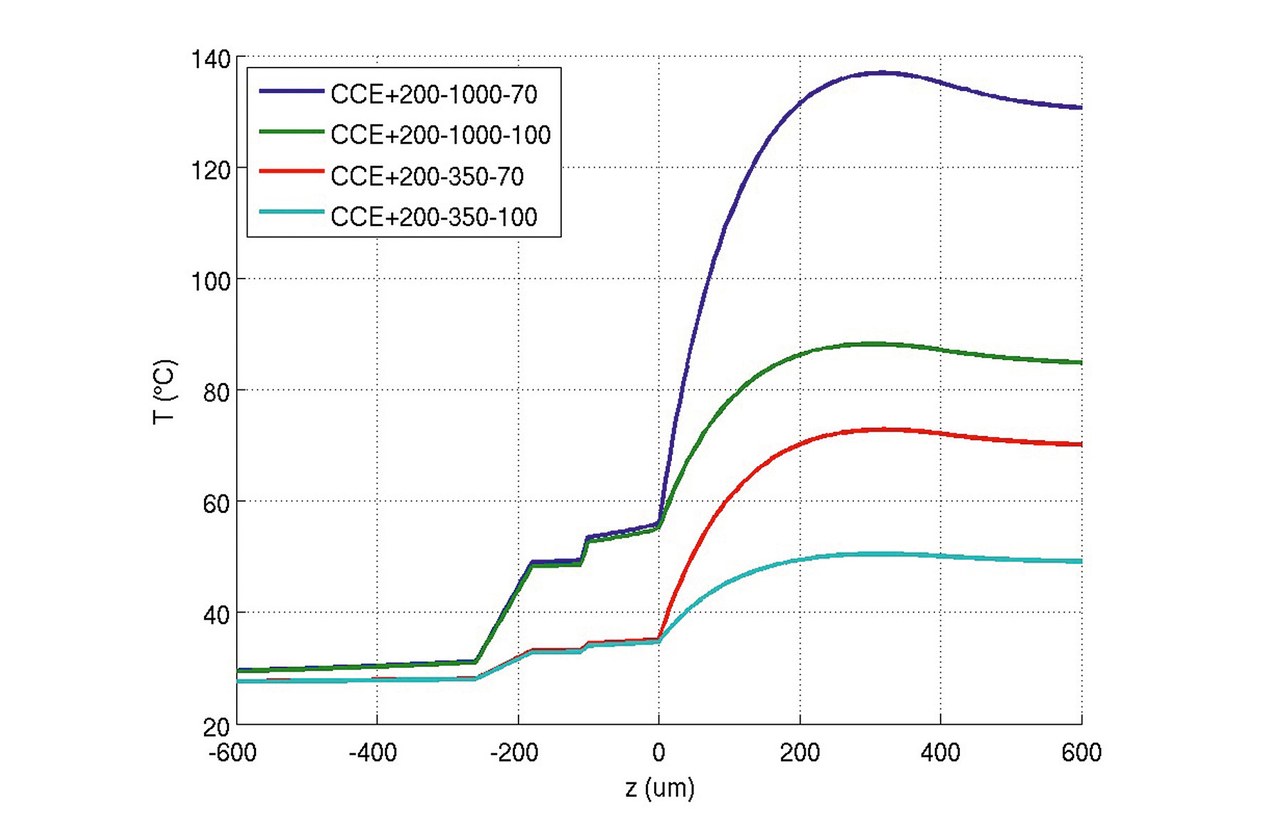
The relevance for a compensation of temperature induced color shifts is highlighted in figure 2, which shows line scans for the temperature profiles along the vertical direction of the LED package assuming that the assembly is mounted on a cooler with a constant temperature of 300 K, the quantum efficiency of the phosphor is either 70% or 100% and that the LED package is operated at either 350 mA or 1000 mA. The LED die is placed on a printed circuit board (PCB) by chip-on-board technology with an adhesive layer having a height of 10 μm. The PCB consists of an aluminum substrate with a height of 1500 μm and a dielectric layer (80 μm) as well as a copper layer (70 μm) on its top. At the assembly’s bottom face (outside the size range shown in figure 2) Dirichlet boundary conditions are considered. All other boundaries of the model are subject to natural air convection.

Figure 2: Line scans for the temperature profiles along the vertical direction of the LED package
In any case, the highest package temperatures are located within the CCE. Bearing in mind that, as recently discussed, a temperature variation of about 40 K (in particular at higher temperature levels) might be just tolerable for CCT variations which do not exceed a MacAdam ellipse of step 2 [11] it is obvious that a compensation of temperature induced color variations is indispensable.

Figure 3: Variation of CIE x values as a function of the quantum efficiency of the phosphor and the refractive index of the silicone for a set-up in accordance with figure 1a
Figure 3 shows the variation of the CIE x values as a function of the quantum efficiency of the phosphor and the refractive index of the silicone for a set-up in accordance with figure 1 a. In this case, the silicone (both for the CCE and the encapsulation layer) is assumed to have a thermo-optic coefficient of -5×10⁻⁴ K-1. The figure shows the variation of the CIE x values at room temperature (n = 1.4) with respect to a decreasing quantum efficiency of the phosphor. In addition, the figure also shows the variations of the CIE x values for the same reductions of the quantum efficiency values, assuming a refractive index of the silicone of 1.35. Latter value represents, in accordance with the thermo-optic coefficient, the refractive index of the system for a temperature that is 100 K higher than the room temperature. Due to the enhanced light scattering, a refractive index of 1.35 gives reason for higher CIE x values, despite a reduction of the quantum efficiency. Still, due to the additional silicone layer, all CIE x values are a little bit lower than those presented in our previous study for the CCE without an additional silicone encapsulation layer [15].
As already mentioned above, such a temperature dependent reduction of the refractive index of the silicone will increase the refractive index difference between the phosphor and the silicone. This will enhance light scattering and is the reason for a more yellowish emission. By itself, this would therefore give reason for some color deviation to the yellowish upon device operation. On the other hand, with increasing temperatures in the CCE, the luminescence intensity of the phosphor will simultaneously decrease. Such a temperature dependent reduction of the luminescence intensity of the phosphor gives reason for a more bluish emission. This means, that by an appropriate matching of the temperature induced luminescence loss of the phosphor and the respective thermo-optic coefficient of the silicone, which have a contrarian temperature dependent effect on the color shift, both effects can be counterbalanced, at least in those temperature ranges, for which the slope of the intensity loss of the phosphor does not become too strong.
As shown, in comparison with the reference system at room temperature, at a 100 K higher temperature, a silicone with a thermo-optic coefficient of 5×10⁻⁴ K-1 and a quantum efficiency value of the phosphor of a little bit more than 92% again results in almost the same CIE x value as the initial system at room temperature.This means that such a thermo- optic coefficient of the silicone in principle can counterbalance about an 8 % reduction of the quantum efficiency value in the temperature range of 100 K for the given set-up.
Figure 4 shows the same dependencies as in case of figure 3. But with respect to the set-up shown in figure 1 b, for which additionally scattering particles are added to the silicone encapsulation layer. The CCE consists of a silicone having a thermo-optic coefficient of -5×10⁻⁴ K-1. The additional silicone encapsulation layer on top of the CCE has the same refractive index and the same thermo-optic coefficient as the silicone used as a matrix for the CCE. The encapsulation layer is filled with 10 vol. % scattering particles. Assuming a refractive index of the silicone of 1.4 and a quantum efficiency of the phosphor of 100% at room temperature, a reduction of the quantum efficiency by more than 8% can be compensated at a 100 K higher temperature. Due to the additional scattering of the light induced by the scattering particles, and in particular due to some back scattering of blue light, which now impinges upon the phosphor particles, the overall emission becomes more yellowish and also slightly higher values of luminescence intensity reduction can be compensated.

Figure 4: Variation of CIE x values as a function of the quantum efficiency of the phosphor and the refractive index of the silicone for a set-up in accordance with figure 1b for which additionally scattering particles are added to the silicone encapsulation layer
Figure 5 shows a combination of silicones with different thermo-optic coefficients, in which it is assumed that either the CCE or the encapsulation layer silicones have thermo-optic coefficients of either -1.5x10⁻⁴ K-1 or -5×10⁻⁴ K-1 (which coincides, as discussed above, with the possible range of thermo- optic coefficients of silicones). In addition, the encapsulation layer is filled with scattering particles
(10 vol. %). The figure shows that different quantum efficiency losses can be compensated in this way. Assuming that the silicone of the CCE has a comparably low thermo-optic coefficient and the encapsulation layer a larger one, a comparably small reduction of the quantum efficiency can be compensated, while in the other case a much larger one can be compensated.

Figure 5: Variation of CIE x values as a function of the quantum efficiency of the phosphor and the refractive index of the silicone for a combination of silicones with different thermo-optic coefficients
Assuming a refractive index of the silicone of 1.4 and a quantum efficiency of the phosphor of 100% at room temperature, different values for temperature dependent luminescence intensity losses of the phosphor can be compensated at a 100 K higher temperature. In addition, a comparison of the cases shown in figure 3 (both layers have a refractive index of 1.35 at a 100 K higher temperature) and figure 4 shows that by such an approach additional values for a possible quantum efficiency loss (as it is determined by a specific phosphor) can be compensated or at least be best fitted to the function for the temperature dependent quantum efficiency loss.
Conclusion
Besides the necessity to consider the thermo-optic coefficients of the materials constituting the CCEs of phosphor converted LEDs for color constancy of phosphor converted LEDs under operation in general, an appropriate adjustment of the thermo-optic coefficients also opens the possibility to accurately counterbalance the temperature dependent luminescence loss of a specific phosphor, at least for a specific temperature range. Thus, besides research on new phosphor materials with higher thermal stabilities in order to reduce the temperature dependent color shift upon device operation, research activities should also focus on matrix materials development with regard to their thermo-optic coefficients. The capability of being able to adjust the thermo-optic coefficient with high precision is of particular importance since, as shown, even small variations of the thermo-optic coefficient again may have a notable impact on color temperature constancy. On the other hand, as shown in the present study, an appropriate combination of two layers of silicones with different thermo-optic coefficients (and/or filling them with different concentrations of scattering particles) can be applied to counterbalance several different levels of temperature induced color variations due to luminescence intensity reduction, which provides an alternative to the synthesis of a lot of different silicones, each of them having a different thermo-optic coefficient.
In addition, such a multilayer approach also has a high potential to be applied in case the CCE consists of two layers with different phosphor materials in order to improve color rendering. For such an attempt it has been shown that a two-layer approach is favorable with respect to mixing both phosphors into one silicone layer [20]. In this case each layer will require a different thermo-optic coefficient of the silicone in order to counterbalance color shifts induced by the respective temperature dependent luminescence intensity losses of the phosphors.
Acknowledgement:
The authors gratefully acknowledge financial support by the Klima- und Energiefonds (KLIEN) and the Österr. Forschungsförderungsgesellschaft mbH (FFG), project no. 843877, iCol.
References:
[1] H. J. Round, H. J. “A note on carborundum”, Electrical World 49: 309, (1907)
[2] N. Zheludev, “The life and times of the LED — a 100-year history”, Nature Photon. 1, 189, (2007)
[3] M. H. Crawford, “LEDs for solid-state lighting: performance challenges and recent advances”. IEEE J. Sel. Top. Quantum Electron. 15, 1028 – 1040, (2009)
[4] E. F. Schubert and J. K. Kim, “Solid-state light sources getting smart”, Science 308, 1274 - 1278, (2005)
[5] J. Brodrick, http://apps1.eere.energy.gov/buildings/publications/pdfs/ssl/feb2013_nema_brodrick.pdf
[6] N. Narendran, L. Deng, R. M. Pysar, Y. Gu, and H. Yu, “Performance characteristics of high-power light-emitting diodes, Proc. of SPIE vol. 5187, 267, (2004)
[7] C. Sommer, P. Hartmann, P. Pachler, M. Schweighart, S. Tasch, G. Leisinig, F. P. Wenzl: “A detailed study on the requirements for angular homogeneity of phosphor converted high power white LED light sources”; Opt. Mater. 31, 837 - 848, (2009)
[8] Z.-Y. Liu, C. Li, B.-H. Yu, Y.-H. Wang, H.-B. Niu, „Effects of YAG:Ce phosphor particle size on luminous flux and angular color uniformity of phosphor-converted white LEDs”, IEEE/OSA J. Disp. Technol. 8, 329 - 335, (2013)
[12] P. Fulmek, C. Sommer, P. Hartmann, P. Pachler, H. Hoschopf, G. Langer, J. Nicolics, F. P. Wenzl, “On the thermal load of the color conversion elements of phosphor based white light emitting diodes”, Adv. Opt. Mater. 1, 753–762, (2013)
[13]X. B. Luo, X. Fu, F. Chen, H. Zheng, “Phosphor self-heating in phosphor converted light emitting diode packaging”, Inter. J. Heat .Mass Transfer, 58, 276 - 281, (2013)
[14] F. P. Wenzl, C. Sommer, P. Hartmann, P. Pachler, H. Hoschopf, G. Langer, P. Fulmek, J. Nicolics, The impact of the non-linearity of the radiant flux on the thermal load of the color conversion elements in phosphor converted LEDs under different current driving schemes, Opt. Express 21, A439 – A449, (2013)
[15]S. Schweitzer, C. Sommer, P. Hartmann, P. Pachler, H. Hoschopf, F. P. Wenzl, “Improvement of color temperature constancy of phosphor converted LEDs by adaption of the thermo-optic coefficients of the color conversion
[19]R. Wynne, J. L. Daneu, T. Y. Fan, „Thermal coefficients of the expansion and refractive index in YAG“, Appl. Opt. 38, 3282 - 3284, (1999) [20]J. P. You, N. T. Tran, F. G. Shi, Light extraction enhanced white light-emitting diodes with multi-layered phosphor configuration, Opt. Express 18, 5055 – 5060, (2010)
