3-Pad LED Flip Chip COB
Wafer level packaging and flip chip design are the most recent trends in LED manufacturing and packaging. These LED types are perfectly suited for producing COB modules. This combination already promises better thermal performance than standard SMD package based products. However, there is still room for improvements. Pao Chen, Director of Research and Development at Flip Chip Opto shows how a 3-pad flip chip LED further reduces thermal resistance, allows higher power and can help to reduce costs.
Recent development of the LED Chip on Board (COB) module with LED flip chips has successfully demonstrated its advantage in having a lower thermal resistance and cheaper packaging costs over the conventional wire-bond LED COB. By lowering the thermal resistance, LED chips are able to perform with lower junction temperatures and have less thermal decay while thermal dissipation is enhanced. Meanwhile, lower thermal resistance also enables the feasibility to increase optical output through the higher driving current.
Comparison of COB Designs
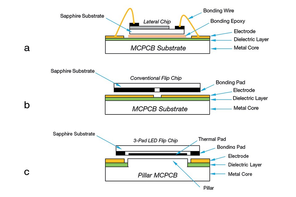
Figure 1(a) and 1(b) show the schematic diagrams of a wire-bond COB and a conventional flip chip COB, respectively. In Figure 1(a), a lateral LED chip is bonded on the metal core printed circuit board (MCPCB) substrate by bonding epoxy and connects to the circuit electrodes via two bonding wires. The thermal energy generated by the LED chip is dissipated through the chips’ sapphire substrate, bonding epoxy, followed by a MCPCB dielectric layer before reaching the metal core. On the other hand, a conventional flip chip COB shown in Figure 1(b) has the LED chip directly bonded on the circuit electrodes without the bonding wire and epoxy. The heat generated by the LED is coupled through the chip bonding pads, circuit electrodes, MCPCB dielectric layer, and then diffused into the metal core. In comparison, the conventional flip chip COB exhibits less thermal resistance as its thermal dissipating path excludes the sapphire substrate and bonding epoxy that are materials having higher thermal resistance. In addition, the packaging cost is reduced without bonding wires and their associated bonding processes. The optical output is also improved without the wire-bonding spots that occupy a partial section of the lighting surface. Meanwhile, some COBs employ ceramic substrate to replace MCPCB for its dielectric character and better thermal conductivity. However, the applications of ceramic-based COB are always restricted due to ceramic’s relatively higher cost and manufacturing limits over the physical size and shape.
3-Pad LED flip chip COB shown in Figure 1(c) is a novel innovation to further reduce the COB thermal resistance, and enable the brightness boost for best lumen-per-dollar performance. The 3-Pad LED flip chip consists of a third contact pad, known as the thermal pad that is electrically isolated and positioned between the N- and P- electrode pads. The thermal pad is designed as a thermal coupling window to optimize the thermal dissipation from the LED’s junction to MCPCB's pillar structure, which appears as an extension of the metal core inside the MCPCB. This arrangement ensures that the entire thermal dissipating path is constructed with highly thermal conductive materials, e.g., metal, alloy, solder, and therefore the thermal resistance between the LED junction and COB bottom is further reduced to minimize the thermal decay.
Thermal Behavior Comparison
Thermal decay is a natural characteristic for LED, as the optical output decreases when the LED junction temperature is increased. Therefore, the lighting efficacy would decrease following the increase of the LED junction temperature while the driving current is increased. In order to minimize the thermal decay, lowering the thermal resistance becomes essential to maintain or lower the LED junction temperature while more optical output is demanded through the increase of driving current. Figure 2 shows the magnitude of efficacy decay measured from a wire-bond ceramic COB and a 3-Pad LED flip chip COB, and their decay results are represented by the red and blue curves respectively. Both COBs were chosen based on their similar overall power consumption and performance specifications of 5000 K CCT and 80 CRI. By comparing the efficacy decay exhibited by both COBs, the decay rate of the 3-Pad LED flip chip COB is roughly about 50% less than the wire-bond ceramic COB. For instance, at 50 W (I=1.3 A) operation, the 3-Pad LED flip Chip COB is able to output 550 more lumen than the ceramic wire-bond COB does due to its lesser efficacy decay. This result highlights the significance of low thermal resistance in maintaining the lighting efficacy while a high driving current is applied for more lighting output.
 Figure 2: A comparison of thermal decay presented by the efficacy decline varying with increasing driving current between a 3-Pad flip hip COB and a ceramic based wire-bond COB
A measurement of LED junction temperature varying with driving current is conducted to evaluate the capability of brightness boost from a 3-Pad LED flip chip COB and a conventional flip chip COB, c.f., Figure 3(a). They are fabricated in the same mechanical dimension (18x18x1 mm) and of the same materials including copper substrate, dielectric layer and circuit trace. Both COBs are mounted on two identical heat sinks during the characterization and each of them consists of twelve 45 mils by 45 mils LED flip chips in series within a Light Emitting Surface (LES) of 12 mm diameter. This characterization is programmed to record the maximal junction temperature at each 100 mA increment under thermal equilibrant condition, and stop when the maximal junction temperature of any COB reaches 125°C. In Figure 3(b), the maximal junction temperature measured from the 3-Pad LED flip chip COB and the conventional flip chip COB are represented by blue and red curves respectively. The difference between two curves starts with 9°C at 400 mA per chip and continues to grow with increasing driving current until the maximal junction temperature of the conventional flip chip COB has reached 123°C at 1000 mA per chip. At this point, the temperature gap has expanded to 17°C. It should be noted that the temperature differential between two COBs reaches 11°C when the driving current is at 700mA. This indicates that the 3-Pad LED flip chip COB owns at least 100% more of the life span than the conventional flip chip COB when the driving current exceeds 700mA, and even longer than that of the wire-bond COB.
 Figure 3: (a) structural diagrams indicating the difference of thermal dissipation between a 3-Pad LED flip chip COB at left and a conventional flip chip COB at right. (b) The maximal junction temperature measured varying with increasing driving current between the 3-Pad LED flip chip COB and the conventional flip chip COB
Assuming that this experimental setup represents a LED luminaire which is limited to the maximal junction temperature at 105°C, the maximal driving current of the conventional flip chip COB is then restricted to 830mA, whereas the maximal driving current for 3-Pad LED flip chip COB is 970 mA. The 3-Pad LED flip chip COB is able to withstand 17% more of the driving current than the conventional flip chip COB, and therefore generates at least 12% more of the optical output. Such capability allows illumination designers to utilize fewer LED chips and smaller optics in the luminaire to achieve the desired brightness.
Phosphor Deposition for CSPs
Typical flip chip COBs are fabricated by dispensing the phosphor epoxy to cover the flip chips that have been bonded onto the MCPCB or ceramic surfaces. An emerging LED flip chip, known as Chip Scale Package (CSP) or White Chip, takes an elegant route to alter the COB manufacture processes. Structure-wise, CSP is a LED flip chip with phosphor materials surrounding all five facets except for the one with contact pads, c.f., Figure 4(a). This approach simplifies the COB manufacturing process without the involvement of dispensing the phosphor epoxy, and takes control of the performance parameters into the chip level instead of the post bonding processes.
The phosphor deposition for the CSP can be conducted either directly onto the LED wafer before dicing, or around each individual chip, or onto the post bonding package via deposition methods such as coating, screen printing, spray deposition, immersion and film lamination. Although those deposition methods are standard in solid state processes, they do share several challenges during phosphor deposition, such as reliability, adhesion strength, radiation pattern control, and color uniformity that is influenced by the thickness of the phosphor layer and the aligning accuracy with flip chips. On the packaging side, COB bonding also needs to overcome issues existing between the CSPs and MCPCB, such as accuracy of bonding alignment, strength against shear force and chemical protection.
Figure 4(b) shows the bottom view of a 3-Pad CSP reflecting on the structural diagram in Figure 4(a), and Figure 4(c) displays a light bar COB having 3-Pad CSPs as its illuminating source. The low thermal resistance exhibited by the 3-Pad LED flip chip is able to maintain phosphor's performance by reducing the contact temperature between the chip and phosphor coating. In principle, each CSP is able to perform independently as a single lighting source of desired spectrum, and also adapts the processes of COB packaging to have the advantages that lower thermal resistance could induce.
 Figure 4: (a) A structural diagram of a 3-Pad Chip Scale Package; (b) bottom view of a 3-Pad Chip Scale Package; (c) a light bar COB having 3-Pad Chip Scale Packages on its surface
Capabilities of 3-Pad LED Flip Chip COBs
3-Pad LED flip chip COB is a proven technology that enables the LED lighting module to output more optical power through its extremely lower thermal resistance. For instance, a 3-Pad LED flip chip COB with 0.007°C/W thermal resistance is able to output 87,850 lumens from an array of 285 LED flip chips within an LES of 85mm diameter. The advanced photon density provides illumination designers the flexibility to design the luminaire with smaller LES and optics. In addition, lower thermal resistance also allows the deployment of inexpensive thermal solutions, such as smaller heat sinks, higher thermal resistant heat sinks, economical thermal interface materials (TIM), and at the same time maintaining the LED junction temperature within its safe range.
Conclusions
Consequently, the 3-Pad LED flip chip COB has demonstrated its capability to optimize a luminaire's lumen-per-dollar value through the approaches such as enhanced optical output and usage of smaller heat sinks, smaller optics and fewer LED chips. Meanwhile, the material saving by utilizing smaller heat sinks, smaller optics and fewer chips also helps to preserve the earth’s non-renewable resources.
