LED driver
A light emitting diode (LED) driver to drive an LED, including a current adjusting unit to adjust magnitude of a current flowing on the LED by supplying power from a power supply device to the LED and cutting off the power. A modulation control unit is provided to modulate a waveform of the current flowing on the LED by controlling the adjustment operation of the current adjusting unit. A constant current offset unit to control the adjustment operation of the current adjusting unit is provided so that the current flowing on the LED is higher or equal to a predetermined value as the waveform thereof is modulated. Thus, provided is an LED driver having improved power consumption efficiency.

Background of the invention
[0002] 1. Field of Invention
[0003] Apparatuses consistent with the present invention relate to a light emitting diode (LED) driver, and more particularly, to an LED driver that can improve efficiency of power consumption.
[0004] 2. Description of the Related Art
[0005] An LED is used as a backlight for a liquid crystal display (LCD), where plural arrays of LEDs are provided for each of three colors, Red, Green and Blue.
[0006] A conventional driver used to drive LEDs can be configured with a circuit as illustrated in FIG. 1. In the driver 1 of FIG. 1, when a switching field effect transistor (FET) 2 is in an ON state, the current supplied by power source 5 flows on an LED 6 through an inductor 3, whereas, when the switching FET 2 is in an OFF state, the current flows on the LEDs by way of the inductor 3 and a diode 4.
[0007] The driver 1 controls the current flowing on the LED (hereinafter shortened as "LED current") to have a predetermined peak value (so called "analog dimming"), and controls the LED current to be ON or OFF, through the use of a pulse width modulation (PWM) signal, having a predetermined duty cycle (so called "PWM dimming"), thereby adjusting luminance of the light emitted by the LED 6.
[0008] The LED current controlled by the driver 1 may be shaped with approximately square waves as illustrated in FIG. 2. If the peak value of the square wave is approximate to the maximum rated current of the LED 6 and its minimum value is approximately 0, the LED current and the average luminance of the LED 6 by the LED current is as illustrated in FIG. 3, by averaging the square waves. Here, an X axis indicates LED current and a Y axis indicates LED light output.
[0009] The average luminance of the LED provided by the LED current, shaped with square waves, is represented in the form of a straight line B, connecting a starting point of X-Y coordinates to the luminance value of the LED corresponding to the maximum rated current of the LED.
[0010] However, when direct current that is approximately constant in magnitude (hereinafter referred to as "constant current": see FIG. 2) flows on the LED 6, the luminance of the LED 6 by the LED current is the same as a curve A depicted in FIG. 3. In this case, a relationship between current and luminance is not linear, but shows an exponential function wherein the light output of the LED 6 is saturated if the LED current is larger than a predetermined magnitude.
[0011] Accordingly, even in the LED current or LED average current having the same magnitude, a difference D1 occurs between the luminance (A) and the average luminance (B) of the LED 6 respectively to the constant current and the square wave current, as depicted in FIG. 3. For example, where the duty cycle of the square wave is 50%, the difference in efficiency between the luminance (A) and the average luminance (B) of the LED 6 respectively to the constant current and the square wave current is about 15% in terms of power.
[0012] As a result, like PWM control under which the LED current is shaped with square waves, controlling the LED current which is a periodical direct current is less efficient than controlling the LED current which is the constant current, in terms of power consumption.
Brief summary of the invention
[0013] Accordingly, it is an aspect of the present invention to provide an LED driver having improved efficiency of power consumption.
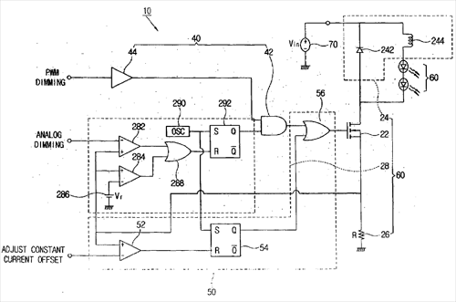
[0014] Additional aspects of the invention will be set forth in part in the description which follows. [0015] In an exemplary embodiment, aspects of the present invention are achieved by providing a light emitting diode (LED) driver to drive an LED, comprising a current adjusting unit to adjust magnitude of a current flowing on the LED by supplying power from a power supply device to the LED and cutting off the power; a modulation control unit to modulate a waveform of the current flowing on the LED by controlling the adjustment operation of the current adjusting unit; and a constant current offset unit to control the adjustment operation of the current adjusting unit so that the current flowing on the LED is higher or equal to a predetermined value as the waveform thereof is modulated. [0016] According to an aspect of the present invention, the current adjusting unit comprises a switching unit to input an ON or OFF signal to thereby supply power to the LED from a power supply device and cut off the power; a regulating unit to regulate the current flowing on the LED so that it is not abruptly changed; a current detecting unit to detect the current flowing on the LED; and a switching control unit to output a signal to turn off the switching unit when the current detected by the current detecting unit is determined to be higher than or equal to a first threshold, but to output a signal to turn on the switching unit when the current detected by the current detecting unit is determined to be less than the first threshold. [0017] According to an aspect of the present invention, the modulation control unit inputs a predetermined pulse width modulation (PWM) signal to thereby supply an output signal of the switching control unit to the switching unit and to cut off the output signal.
[0018] According to an aspect of the present invention, the constant current offset unit outputs a signal to turn off the switching unit when the current flowing on the LED detected by the current detecting unit is determined to be higher than or equal to a second threshold and the output signal from the switching control unit is cut off, but outputs a signal to turn on the switching unit when the current flowing on the LED is determined to be less than the second threshold.
[0019] According to an aspect of the present invention, the constant current offset unit comprises a comparator to compare a voltage corresponding to the current flowing on the LED, which is detected by the current detecting unit, with a voltage corresponding to the second threshold, and output a logic HIGH signal when the voltage corresponding to the current flowing on the LED is higher; a set-reset (S-R) flip flop to set an output signal from the comparator as a RESET input and a pulse signal having a predetermined frequency as a SET input; and an OR gate to receive an output signal from the S-R flip flop and an output signal from the modulation control unit, outputting the logical sum of the received output signals to the switching unit.
Claims
1. A light emitting diode (LED) driver to drive an LED, comprising: a current adjusting unit which performs an adjustment operation to adjust magnitude of a current flowing on the LED by supplying power from a power supply device to the LED and cutting off the power; a modulation control unit to modulate a waveform of the current flowing on the LED by controlling the adjustment operation of the current adjusting unit; and a constant current offset unit to control the adjustment operation of the current adjusting unit so that the current flowing on the LED is higher or equal to a predetermined value as the waveform thereof is modulated.
2. The LED driver according to claim 1, wherein the current adjusting unit comprises: a switching unit to input an ON or OFF signal to thereby supply the power to the LED from the power supply device and cut off the power; a regulating unit to regulate the current flowing on the LED so that it is not abruptly changed; a current detecting unit to detect the current flowing on the LED; and a switching control unit to output a signal to turn off the switching unit when the current detected by the current detecting unit is determined to be higher than or equal to a first threshold, and the switching control unit to output a signal to turn on the switching unit when the current detected by the current detecting unit is determined to be less than the first threshold.
3. The LED driver according to claim 2, wherein the modulation control unit inputs a predetermined pulse width modulation (PWM) signal to supply an output signal of the switching control unit to the switching unit and to cut off the output signal.
4. The LED driver according to claim 3, wherein the constant current offset unit outputs a signal to turn off the switching unit when the current flowing on the LED detected by the current detecting unit is determined to be higher than or equal to a second threshold and the output signal from the switching control unit is cut off, and the constant current offset unit outputs a signal to turn on the switching unit when the current flowing on the LED is determined to be less than the second threshold.
5. The LED driver according to claim 4, wherein the constant current offset unit comprises: a comparator to compare a voltage corresponding to the current flowing on the LED, which is detected by the current detecting unit, with a voltage corresponding to the second threshold, and to output a logic HIGH signal when the voltage corresponding to the current flowing on the LED is higher; a set-reset (S-R) flip flop to set an output signal from the comparator as a RESET input and a pulse signal having a predetermined frequency as a SET input; and an OR gate to receive an output signal from the S-R flip flop and an output signal from the modulation control unit, outputting the logical sum of the received output signals to the switching unit.
See full document in pdf.
