The Right Choice of Current-Limiting Resistors for Constant Voltage LED Drivers
While LEDs are mostly driven by current sources, there are also several applications where constant voltage drivers are used. In that case current limiting resistors are mandatory. But that raises the question which resistor is the right one to guarantee reliable and accurate control while not compromising efficiency. Phil Ebbert, VP of Engineering at Riedon Inc. explains what to take care of and how to determine the correct parameters.
")
Introduction:
Not all resistors are the same and growth in new markets like high-power LED lighting is serving to highlight the importance of understanding all aspects of an application in order to correctly and safely specify the right type of resistor.
Consequently, this article will first return to basics to understand the operating principles of LEDs and how they need to be correctly biased to achieve the optimum light output performance specified by the manufacturers. This will look at the electrical, optical and thermal characteristics of LEDs to appreciate why driving several LEDs in series can be more efficient than overdriving single LEDs, and why keeping temperatures in check is not just key to maximizing output but also to maintaining the desired color tone and ensuring reliability and long life.
Having understood the biasing calculations for some typical lighting scenarios, it quickly becomes apparent that in many applications the necessary ballast resistor is likely to dissipate several Watts of power. This not only dictates the need for a suitable high-power resistor type but may call for a design suitable for mounting on a heat sink, to help carry heat away from the LED rather than contribute to an already challenging design requirement.
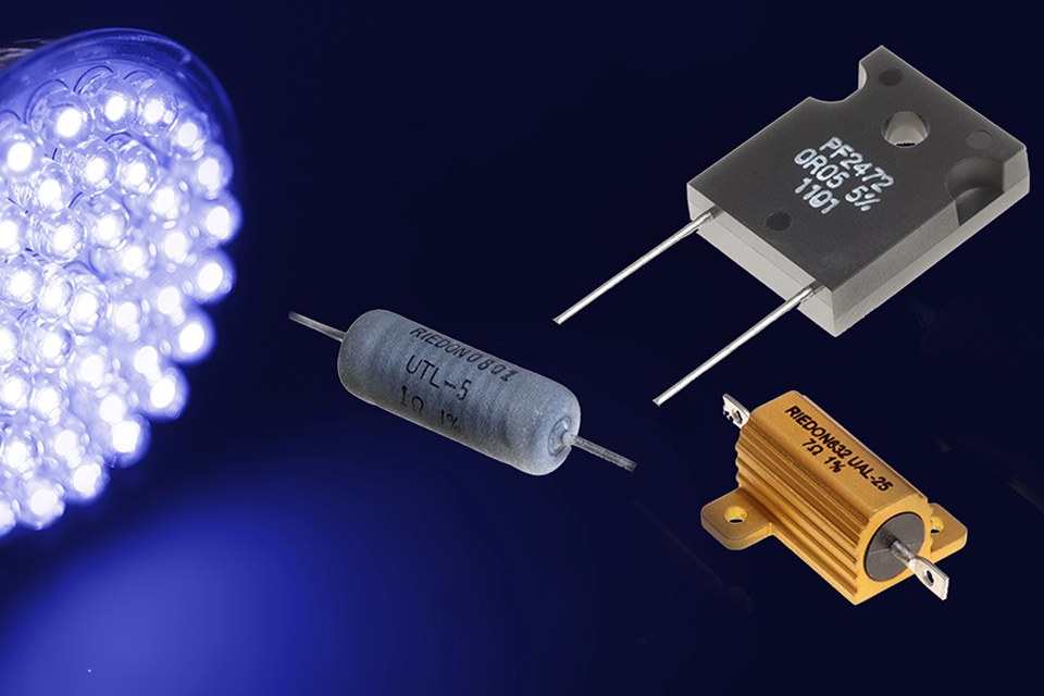
All these considerations and more will be explored in the context of potential design solutions from specialist resistor manufacturer and supplier, Riedon, whose product line includes its UT series of wirewound power resistor for up to 13W dissipation, its PF series of power film resistor with ratings up to 20W and other series that allow for additional heatsinking and surface mount options.
Understanding LED operation and biasing requirements:
A light emitting diode (LED) is a type of semiconductor diode that emits light when a current flows from anode to cathode across the P-N junction of the device. Hence, in normal operation, an LED requires a direct current (DC) supply to provide the necessary positive bias (forward voltage) across this junction.
High brightness LEDs intended for lighting applications typically deliver optimum performance with a forward voltage of around 3V. However, as can be seen in figure 1, the relationship of voltage to current is non-linear so while the LED will start to turn on at a lower voltage it will rapidly draw a much higher current as the voltage increases above its nominal rating. Apart from considerations of heat dissipation and reliability (more on this below), this is inefficient since the relationship of luminous flux (a measure of light output) with LED current is also non-linear. So a doubling of current certainly does not result in twice the light output and a far better solution to achieve the desired light output is to use multiple LEDs.
 Figure 1: Typical LED current versus voltage characteristic
Given these characteristics, the conventional solution for driving LEDs is to control the current through the device and the simplest method, as shown in figure 2, employs a series resistor to limit current such that, using Ohm’s Law:
IF = (VDC – VF)/R
where IF = forward current
VDC = supply voltage
VF = forward voltage
R = ballast resistor
 Figure 2: Simple LED biasing circuit
It is possible to use a rectified and smoothed mains input to power the LED bias circuit but the resulting supply voltage (VDC) will be much higher than the forward voltage (VF) across a single LED, meaning that considerable power would be wasted in the ballast resistor compared to the power consumed by the LED. Connecting a number of LEDs in series, which is typical of many LED lamp designs, only partially addresses the issue, as the cumulative forward voltage will still be less that the voltage dropped across the resistor.
Instead most LED lighting systems employ power supply units (PSUs) with dedicated LED driver circuits providing an output to suit the required LED configuration. These PSUs typically accept AC mains input with a DC output that may drive a single LED but more likely a string of LEDs operating at voltages up to 60V. Even the “60W replacement” type of LED bulb uses a built-in LED driver circuit to convert AC mains to a suitable DC voltage to power its LEDs. Using dedicated power supplies also allows the connection of LEDs or LED strings in parallel for distributed lighting systems but normally the current in each parallel path still needs to be limited by a separate series resistor.
Ballast resistor selection considerations:
We can most readily understand this by performing some simple calculations based on the bias circuit and LED characteristics shown above. For example, using a 24V DC supply and six LEDs connected in series (each with a nominal forward voltage of 3V) leaves us with 6V to be dropped across the ballast resistor. So, with a corresponding LED forward current of 350mA, the required resistor value is given by:
R = (VDC – 6 x VF) / IF = (24 – 6 x 3) / 0.35 = 17.1Ω (ohms)
And, the power that the resistor has to dissipate is given by:
P = V x I = 6 x 0.35 = 2.1W (watts)
This provides the baseline specification for the resistor but before moving on to see what type of resistor might be suitable it is perhaps useful to question some of our assumptions. Such as, why a 24V supply when clearly a 20V supply would reduce the power dissipation in the resistor to just 0.7W? One reason lies with design and component tolerances. A typical PSU may have an output voltage tolerance of ±5% and, while the current / voltage characteristic of the LEDs is still a factor, most of the output variation will affect the voltage across the resistor. Hence in our example with a 24V PSU an increase of +5% (+1.2V) will result in a current increase to around 400mA, which is still close to nominal for the LEDs. However with a 20V PSU a +5% increase (+1V) takes the forward current to around 450mA, which is disproportionally higher than the target 350mA.
Similar effects on the forward current will result if the resistor value itself deviates significantly from the design target value or if the LEDs vary from their nominal characteristics. Although there are no absolute rules for the design of LED bias circuits, all these factors need to be taken into account. The penalty, as noted earlier, is that the increased power dissipation from operating at higher currents leads to higher LED junction temperatures. This results in reduced relative light output, which partly negates any increase from operating at a higher current, but more importantly impacts on the device’s reliability and expected lifetime.
The relative chromaticity, i.e. color tone, of an LED is also affected by variations in current and temperature and is another reason for keeping both under control. This raises the issue of LED dimming since, although it is possible to achieve analog dimming of LEDs over a limited brightness range by varying the drive current, sometimes even beyond its nominal rating, this comes with the same problem of color variations. Instead the preferred method is pulse-width modulation (PWM) of the bias current. This approach typically drives the LEDs with a rectangular waveform, effectively switching the LEDs on and off at a rate (100kHz or more) which is too high to be noticed. In this way the LEDs see the ideal nominal forward current during the ‘on’ part of the cycle and there is negligible power dissipation during the ‘off’ phase. The potential requirement for PWM dimming does however impose another constraint on the choice of ballast resistor; namely that it needs to be a non-reactive load i.e. with minimal inductance or capacitance.
Potential types of resistor for LED ballasts:
For LED lighting applications, devices with a nominal rated forward current of 350mA are quite typical but LEDs designed for operation at 700mA, 1A and even 1.5A are becoming increasingly common. So where the application example discussed above requires a resistor with a rating just over 2W, higher power LEDs may well require resistors rated at 10W or more.
Axial-leaded wirewound resistors offer reasonable power handling with low resistance tolerances, excellent low TCR (temperature coefficient of resistance) performance and they can operate over a wide temperature range. For example, Riedon’s UT series wirewound power resistor offers power ratings up to 13W and a temperature range of -55oC to +250oC (or even +350oC for some types). For even higher power dissipation, or where it is important to remove heat more effectively from the ballast resistor, Riedon has its UAL series of aluminum-housed wirewound power resistor with ratings to 50W and above.
Wirewound resistors are available with non-inductive windings but thin film resistor technology provides an alternative that may suit some applications. Riedon’s PF series offers low-inductance power film resistors in various package housings to support different power ratings e.g. 20W TO-126 and 50W TO-220. For surface mount designs the PFS series of power SMD film resistor from Riedon can handle up to 35W.
 About the Author:
Phil Ebbert – VP of Engineering, Riedon Inc.:
Phil Ebbert is in charge of resistor development at Riedon Inc. He is also responsible for its technology projects, including equipment, testing and process design. Mr. Ebbert has 15 years resistor engineering experience and led Riedon’s expansion from wirewound resistors into related film and foil technologies. He studied physics, optics, and computer science at Carnegie Mellon University.
