230 VAC Driven LED Modules with Strongly Reduced Flicker, by euroLighting
One of the continuing trends in LED lighting is toward AC driven LED modules. Big progress has been made regarding dimmability and reduction of flicker. However, there are still differences in the various concepts that lead to very different results. Wolfgang Endrich, founder and managing director of euroLighting presents a recently improved new concept to significantly reduce flicker.

The US Ministry of Energy (DOE) has forecasted in their annual F&E plan regarding solid state lighting 2015 that by 2030 about 80% of all luminaires in the United States will be operating with LED. This would create a reduction of about 60% in the consumption of electricity. Even the losses by the LED driver could add up to 10% or more and the failure rate of the LED driver is up to 52% for Asian products. Therefore the US Ministry of Energy recommends the usage of AC-LED driver technology and called it the “coming next generation of light sources”.
Designing a new LED luminaire poses great challenges today – including selecting the right LEDs and a suitable power supply unit. The new AC technology has now substantially simplified this process: It allows direct control of the LEDs with 230 V AC and generates virtually flicker-free light with very good dimming properties.
Having to develop a dedicated power supply unit can significantly delay a new project. It is much easier now to use the new AC technology with direct control through 230 V AC – with obvious advantages: In addition to considerable cost reductions, LEDs from different manufacturers can be used and combined in one circuit. It is now possible to use a much smaller power supply unit which can be integrated unobtrusively into any housing and can be included already on the PCB of the LED.
Direct Control with 230 V
Directly controlling an LED with 230 VAC may sound puzzling especially with regard to the so-called safety extra low voltage. Appropriate safety measures and insulation can quickly dispel these doubts. The newly designed IC, the IC EL01, allows LED driver circuits to be operated directly with 230 VAC while generating almost flicker-free light. The 230 V mains AC power is rectified and fed into an AC direct driver without smoothing.
The driver pulses with 100 – 120 Hz and operates the LEDs with constant current and a voltage between 40 – 70 VDC. This produces the advantage that LEDs from different manufacturers specified for voltages between 2 and 70 V can be controlled directly. With an operating voltage of 70 V, numerous DC LEDs with different voltages (max. 70 V) can be directly operated in a group. So if an LED has an operating voltage of, for example, 2 V, up to 35 LEDs of this type can be connected in series. The circuit and the required power input can easily be expanded through the use of further ICs.

Figure 1: AC driving mode with the new designed IC
Different Dimming Concepts
In Germany and in Asian countries, numerous products have already been equipped with AC technology for many years. It has proven successful, e.g. in retrofit lamps, GU10, ceiling spotlights, ceiling floodlights up to 120 W, area luminaires with 62 x 62 cm and LED tubes. The market also offers numerous ICs that can be used to implement AC direct circuits. They have one significant difference, though: These circuits can generally be dimmed, but in two ways.
New concept using multiple new designed ICs
The new IC and the circuit created with it, allows simultaneous dimming of the entire luminaire. That means all LEDs are dimmed evenly (Figures 2a-e).
Figures 2 show that the EL01 LED modules can easily be dimmed without changing the luminous flux modulation - Luminous flux modulation dimmed to 5 W (a), dimmed to 2 W (b), dimmed to 1 W (c), EL01 Chips are mounted all around the edge (d), leading to an even thermal distribution (e).
, dimmed to 2 W (b), dimmed to 1 W (c), chips are mounted all around the edge (d), leading to an even thermal distribution (e). Many other AC concepts use a sequential dimming concept with just one central IC")
Figure 2 a-e: The EL01 LED modules dimmed to 5 W (a), dimmed to 2 W (b), dimmed to 1 W (c), chips are mounted all around the edge (d), leading to an even thermal distribution (e). Many other AC concepts use a sequential dimming concept with just one central IC
Reference concept using one IC for sequential dimming
The most common approach is to implement sequential dimming of individual assemblies. This involves supplying individual groups with full power and adding more groups if more brightness is required. This has certain disadvantages: Not all LEDs can be dimmed at the same time so that the thermal load varies and is not distributed evenly across the entire area. The circuit created with this system uses only one central IC.
The dimming of a conventional AC driven LED module using the sequential dimming approach for example dimmed to 6 W results in a luminous flux modulation of approx. 9 ms with some LEDs being already less bright. Dimmed to 4 W, some LEDs are completely off. The placement of the IC and such a concept can also result also in an uneven heat dissipation, where hot spots can appear.
The new concept uses several ICs which ensures an even thermal load. This makes a useful life of 50,000 h absolutely realistic. Furthermore, this IC features an NTC characteristic which reduces the full power from 85° C to prevent overheating. Long-term tests with these components of over 30,000 hours have shown many advantages: A greatly simplified circuit without electrolytic capacitors and inductivities or transformers. The useful life of the circuit corresponds to that of LEDs with > 50,000 hours, uniform dimmability of the circuit without additional circuitry components as well as flicker-free light at all power levels.
About Flicker-Free AC Lighting
Questions about flicker-free light, especially AC light, and how to measure and to specify it, may arise at this point. To be fair, it should be pointed out that fluorescent tubes operated with conventional or low loss magnetic ballasts also flicker at 100 Hz and the light output is reduced at lower ambient temperatures. Fluorescent lamps operated with an ECG, including energy saving lamps work at 40 – 50 kHz so that the lamps normally do not flicker visibly.
In reality, however, things are a little bit different. While a higher switching frequency is used, the input capacitors are often too small for cost reasons. This causes the high frequency circuit in the lamp to be supplied with a strongly pulsating voltage. This pulsation creates a brightness modulation in the emitted light, which is why these lamps often have a rather high level of flicker at 100 Hz.
As already mentioned, all conventional light sources - including incandescent, high intensity discharge (HID) and fluorescent – modulate luminous flux and intensity, whether perceptible or not. Many terms are used when referring to this time-variation, including flicker, flutter and shimmer. The flicker produced by electric light sources can be a function of how it converts AC electricity to light. It can also be the result of noise of transient events on AC distribution lines.
Electrical flicker should not be confused with photometric flicker, which is the characteristic modulation of the light source caused by electrical input rather than disturbances. Light source characteristics that can affect photometric flicker vary by technology. For LEDs, flicker characteristics are primarily a function of the LED driver.
Photometric flicker from magnetically-ballasted fluorescent, metal halide and high pressure sodium lamps has been a concern of the lighting community because of its potential human impact which range from distraction or mild annoyance to neurological problems. The effects of flicker are dependent on the light modulation characteristics of the given source, the ambient light conditions, the sensitivity of the individuals using the space, and the tasks performed. Low-frequency flicker can induce seizures in people with photosensitive epilepsy, and the flicker in magnetically-ballasted fluorescent lamps used for office lighting has been linked to headaches, fatigue, blurred vision, eyestrain, and reduced visual task performance for certain populations. Flicker can also produce hazardous phantom array effects.
Back to the AC circuits: 100% flicker-free light only comes from the sun: Even traditional filament light bulbs just offer and nearly flicker-free light. However, there are considerable differences between the chip solutions of the compared concepts.
Flicker fusion threshold
When evaluating temporal uniformity as a quality criterion for lighting, fast and slow changes have to be considered separately. Fast changes are the temporal fluctuation of luminous flux of the emitted light due to the pulsating fluctuations of the input, e.g. with AC operation. A crucial factor for whether this fluctuation is perceived as irritating is the flicker fusion threshold of the eye, which also depends on individual circumstances. If the frequency of the luminous flux modulation is above this fusion threshold we can no longer perceive it. This limit frequency, where periodically occurring stimuli are just starting to be perceived as a stimulus, is called flicker fusion threshold and is below 100 Hz for most individuals while a good part - I believe over 50% - of the people don’t even recognize flicker above 70 Hz. Therefore, the relevant flicker frequency for many applications is recognized to be approximately around these 70 Hz. It is also referred to as pulsation. Below this fusion threshold, however, the luminous flux modulation is perceived as an irritating flicker. Eyes are particularly sensitive to this in peripheral vision. Fast moving objects (e.g. lathes) can additionally create stroboscopic effects with the resulting phantom array effect.
Relatively slow changes (in the domain of seconds to minutes) in illumination can have a rather positive influence on the human state of mind. The variability of lighting through artificial indoor lighting systems is only slowly gaining significance as a quality aspect. Monotonous constant lighting creates a tiring effect in the long term and has no positive influence on concentration and efficiency.
There is DC and (DC + AC) light. The following formula applies for dimming LEDs with the usual pulse width modulation (PWM), which is typically a (DC + AC) light:
W = (φmax - φmin ) / φmean_WLED =
within ≤ 1 W < ∞
Disadvantage:
This creates a considerable luminous flux modulation (Figure 3).

Figure 3: Flux modulation in a PWM system
Criteria for good flicker-free light
Two criteria are important for good lighting: The clock frequency of the LEDs has to be well above the flicker fusion threshold. The direct AC control for concept 1 as described has a frequency of 100 Hz. Furthermore, the light intensity should be as uniform as possible. That means rectangular light intensities create a balanced light while wedge-shaped light peaks are perceived as irritating. (Figures 4 a + b).
Figures 4 a & b demonstrate the light fluctuations of different AC driven LED modules. EL01 LED module from euroLighting: trapezoidal light curve (a), LED module from a different manufacturer: wedge-shaped light peaks (b); (luminous flux modulation is measured with an ultrafast photodiode. Normal operation and dimmed).
, LED module using a conventional concept: wedge-shaped light peaks (b) (luminous flux modulation is measured with an ultrafast photodiode in normal operation and dimmed)")
Figure 4 a&b: Light fluctuations of different AC driven LED modules. The new concept: trapezoidal light curve (a), LED module using a conventional concept: wedge-shaped light peaks (b) (luminous flux modulation is measured with an ultrafast photodiode in normal operation and dimmed)
Quantifying Flicker
After all considerations about the theory we will explain in the following how to measure the flicker. A very interesting report was issued by the “US Department of Energy – Energy Efficiency & Renewable Energy”. The following explanations will refer to this report and the direct fact sheet [1].
The following will refer on the basis of this “fact sheet”:
The percentage of flicker at the modulation index and the flicker index. But the result will be the realization that there is not a good or a bad flicker. It really depends on the application whether it is indoor or outdoor usage and finally the human being.
Low flicker sources should always be used for both ambient lighting and task lighting in offices, classrooms, laboratories, corridors, and industrial spaces. Minimizing flicker is especially important where susceptible populations spend considerable time such as hospitals, clinics, medical offices, classrooms, and daycare centers. In contrast, flicker may be less of a concern for parking lots, roadways, or other exterior lighting where light levels are lower and people spend less time.
In the above mentioned report of the US Department of Energy show a very good example to explain what we are talking about now.
How to Measure Flicker
Three analysis methods are suitable and relevant for the calculation of photometrical flicker, which may not be mixed up with voltage or current flickering in electric circuits. These are the flicker index and percent flicker, and less common the modulation index. All three methods have in common that they are relative measures. The flicker index takes into account the waveform of the light output as well as its amplitude according to the handbook. The flicker index assumes values from 0 to 1.0, with 0 for steady light output. Higher values indicate an increased possibility of noticeable lamp flicker, as well as stroboscopic effect. Percent flicker and the flicker index are used to compare the new technology with a conventional AC module.
")
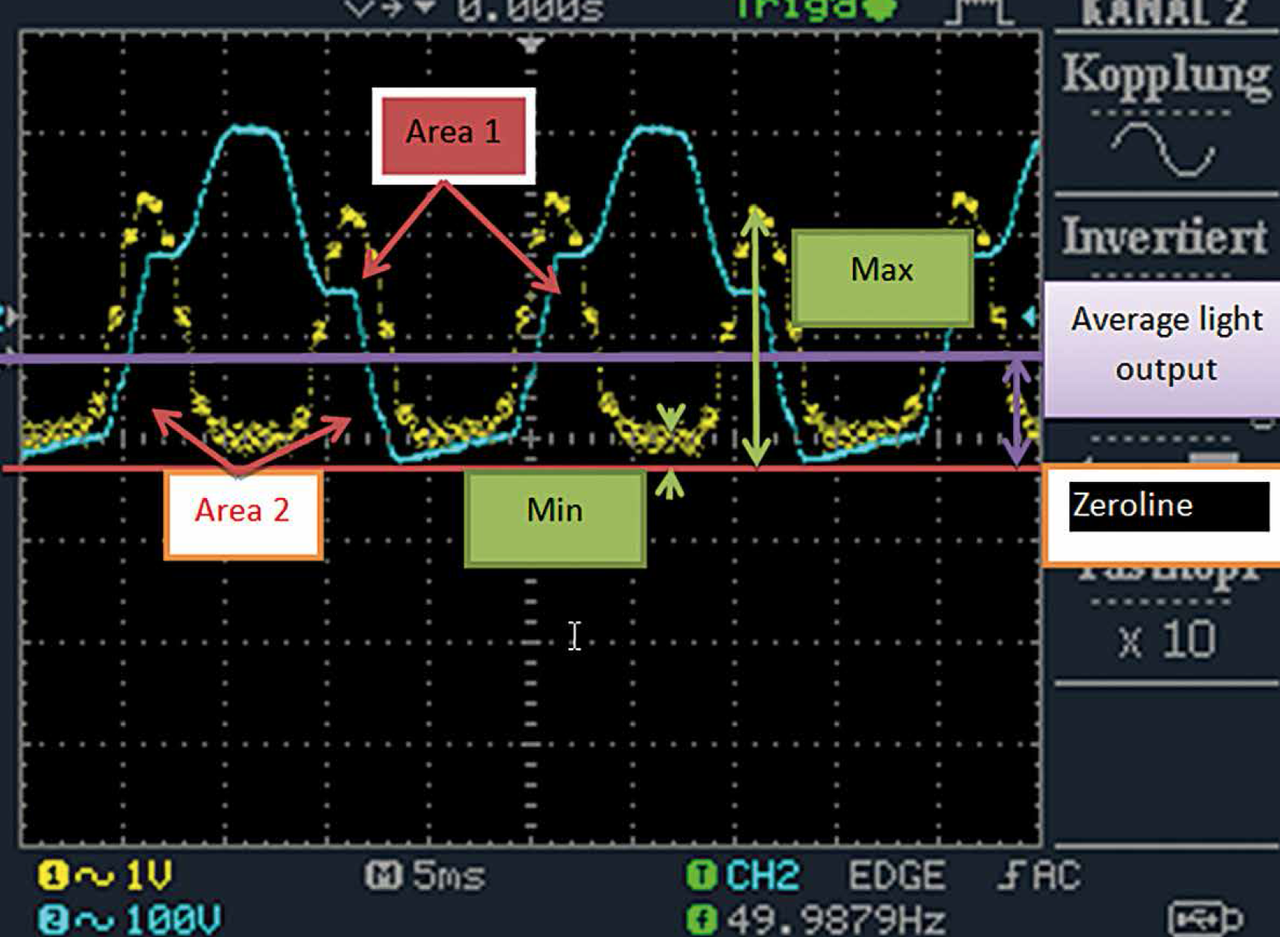
Figure 5: Periodic wave form characteristics used in the calculation of flicker metrics (modified from IES Lighting Handbook, 10th Edition)
In figure 5 the yellow line shows the luminous ripple and the blue curve shows the current. The zero line is the red line and the violet line is the average light output.
Figures 6 a & b show two trapezoid light output waveforms and the related flicker parameters as flicker index and flicker %.

Figures 6 a&b: Two trapezoid light output waveforms and the related flicker parameters as flicker index and flicker %
Flicker indices and flicker percentages of the examples from figures 6 a + b:
Flicker Index for Figure 6 a
Fi = Area 1 / (Area 1 + Area 2) =
9 / ( 9 + 19) = 0,32
Percentage of Flicker for Figure 6 a
F% = (Max - Min) / (Max + Min) x 100% =
(2,3 - 0,5) / (2,3 + 0,5) x 100% = 64,3 %
Flicker Index for Figure 6 b
Fi = Area 1 / (Area 1 + Area 2)=
1 / (1 + 3) = 0,25
Percentage of Flicker for Figure 6b
F% = (Max - Min) / (Max + Min) x 100% =
( 2,4 - 0,3 ) / ( 2,4 + 0,3) x 100% = 77,8 %
A comparison of the measurement diagrams in figures 6 a & b and figure 7 show the distinct different shapes of the light output waveforms (yellow lines). While the waveforms in the figures 6 a & b are trapezoid shaped, the waveform in figure 7 is peak-shaped. All measurements were made with AC driver ICs under the same conditions and may give an idea which light output curve better suites the requirements for the human eyes. It is the trapezoid shape with its bigger amount of light above the average light output line. This means that area 1 is larger. Therefore the flicker will be much less visible.

Figure 7: A more peak-shaped waveform of the light output from another AC driven approach
Final Remarks
The report of the US Department of Energy comes to the conclusion that flicker is creating increasing attention from manufacturers, as well as the standards and specification community. Some manufacturers appear to be giving flicker increased design priority, as evidenced by the improved performance of new product generations. The IES and CIE are considering the development of measurement standards, and IEEE group is working on recommended practices for evaluating flicker risks. Collectively, these efforts may make it easier for designers and specifiers to minimize the risk of flicker-induced problems for their clients in the near future.
References
[1] SSL.energy.gov - the direct fact sheet feedback to: SSL.Fact.Sheets@pnnl.gov.
