A New Approach to the Design of Driverless AC LED Light Engines
Driverless AC LED light engines have now become a commonplace item of commerce in the lighting industry. Nearly all of them use high voltage integrated circuit switching chips to intelligently change the number of LEDs in a string during a power line cycle so that the voltage of the LED string matches the instantaneous power line voltage. However, customers are demanding higher efficiency, lower cost, and especially a reduction in the flicker content of the emitted light. Peter W. Shackle, president of the consulting company, Photalume, describes some new circuits for AC LED light engines [1] that provide a non-dimming solution with reduced cost, increased efficiency and better light quality as perceived by the human eye.
Up until now, the principle practice for AC LED Light Engines was to use switches during the voltage variations of the power line voltage cycle to adjust the number of LEDs present to roughly equal the instantaneous power line voltage, and then use resistors and/or current limiters to keep the LED current at a desired level until the next switch operation. This principle has the disadvantage that some power is always being dissipated, limiting the efficiency to 75%- 80%, and inevitably the output current comes in the form of a series of half sinewaves. In particular with 50 Hz power, the presence of these half sinewave pulses of current at twice the power line frequency produces a flicker effect which some people can see out of the corner of their eye, and in the worst case may produce eye strain and headaches.
The alternative principle introduced here is to have the LED current limited by resistance for a part of the time, and limited by capacitance for the remainder.
Thus, in every power line half cycle there are two pulses of current through the LEDs, first a pulse of displacement current and then a pulse of galvanic current. In each complete power line cycle there are four peaks, so the resulting ripple can be mainly at four times the power line frequency. For power levels below 5 W, where the US Energy Star rules do not require a minimum power factor, it is possible to have continuous DC current with the entire ripple at four times the power line frequency. At higher power levels where a minimum power factor of 0.7 is required, the output LED current ripple has a superior flicker index compared to the conventional circuits, with 87% efficiency and without using any expensive high voltage integrated circuits.
Introduction to the Field of AC LED Light Engines IAC LED light engines are attractive because of their simplicity and relatively low cost for the luminaire designer. Today they are becoming ubiquitous in hallway lighting, decorative lighting, parking lots and an increasing host of other applications. As will be explained in detail below, most of these products are using high voltage integrated circuits which, for each part of the power line voltage cycle, automatically connect the correct number of LEDs to match the power line voltage. An electronic current limiter is used to maintain a constant current between switch operations. Commonly, three stages of switching are used, although two stage and four stage products exist. Since voltage is being dropped across the current limiter, power is being dissipated, which limits the efficiency attainable. Dimming can be achieved by varying the current level programmed for each stage of switching.
The design of AC LED light engines involves numerous compromises. For example, efficiency, power factor and light quality as measured by flicker index all trade off against each other, such that if one is optimized the others usually suffer. Including dimming capabilities requires additional compromises and usually increases cost and complexity. It has become conventional to adopt a set of trade-offs that accompany the use of a high voltage integrated circuit required to allow dimming. Typical of such a compromise in today’s marketplace would be a flicker index (see below) of 0.32, efficiency of 78% and power factor of 98%. This compromise, namely poor flicker index and average efficiency, is affected heavily by the inclusion of dimming, which is not needed for a large number of applications. Without the dimming requirement, the expensive high voltage chip can be eliminated, reducing cost, the flicker index can be reduced and the efficiency can be increased to over 90%. The power levels involved dictate the best way to accomplish this. Below 5 W of input power, Energy Star in the USA does not have a power factor requirement. In this case a solution is described which has superb light quality and over 90% efficiency. When the input power is over
5 W, the power factor for consumer products must be greater than 0.7. In this case a solution is described which also has greater than 90% efficiency and still has superior flicker performance compared to today’s conventional products.
Terminology Used in Characterizing AC LED Light Engines
In the discussion below we shall repeatedly use the terms “efficiency”, “power factor” and “flicker index”.
Efficiency = (power delivered to LEDs) / (Input power to the device)
expressed as a percentage.
Power factor = (input power) / (rms input voltage * rms input current)
This is customarily expressed as a fraction, although sometimes you may see it as a percentage. A perfectly sinusoidal power line voltage driving a resistor will have a power factor of 1.0. A perfect capacitor or inductor connected across the power line, drawing no power, would have a power factor of zero. If the power factor of a device is low, it means that the power being drawn is not commensurate with the current being drawn, because the current is out of phase with the voltage. Energy Star rules in the USA have no power factor requirement for input power below 5 W, and above 5 W the minimum that will be approved is 0.70 for residential/ consumer applications.
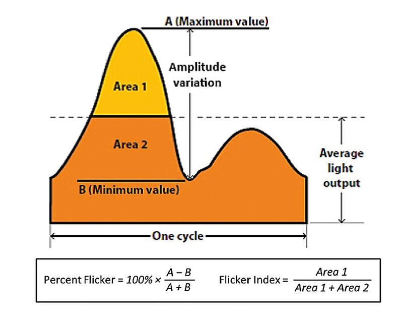
Figure 1: Definition of flicker index (modified from the IESNA handbook, 2010)
Flicker index is defined in figure 1. At low power levels the light output from LEDs is directly proportional to the LED current. A square wave light output with 50% duty cycle will have a flicker index of 0.5, whereas an LED light running off DC will have a flicker index of zero. For reference, an incandescent light bulb typically has a flicker index of 0.15. The flicker index does not have any frequency dependency, whereas the human eye has sensitivity which declines with increasing frequency. For this reason there is need for a new, frequency dependent measure of flicker, but currently none exists. For the time being the flicker index is widely used as a point of reference.
The History of AC LED Light Engines
The earliest circuit used for AC LED light engines is shown in figure 2.
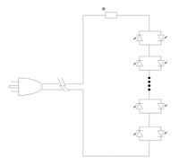
Figure 2: The earliest AC LED circuit
In this circuit the LEDs are arranged in antiparallel to each other. A sufficient number of these antiparallel mounted pairs are connected in series so that their forward voltage is comparable to the peak of the power line voltage. At the peak of the power line voltage waveform current passes through the LEDs and is limited by the resistor R. Such circuits can have high power factor because the current passes in phase with the power line voltage, and if R is relatively small then the efficiency can be as high as 95%. However the flicker index is typically up around 0.45, because most of the time no light is produced and then a brilliant flash is released at each power line voltage peak. This kind of circuit is widely used for Christmas tree lights. A disadvantage of this circuit for general lighting is that a lot of LEDs are being used, and at any one time, half of them are dark. These circuits were replaced in general lighting by the circuit
shown in figure 3.
In this second generation circuit, a bridge rectifier is used to halve the number of LEDs needed. As before, a resistor is used to limit the current at the peak of the line. The efficiency, power factor and flicker index are essentially unchanged. In this and all the AC LED circuits described in this article, it is necessary to have surge protection circuitry of some kind present to protect the LED circuit from power line surges which may arise from power line switching, lightning induced surges, etc.
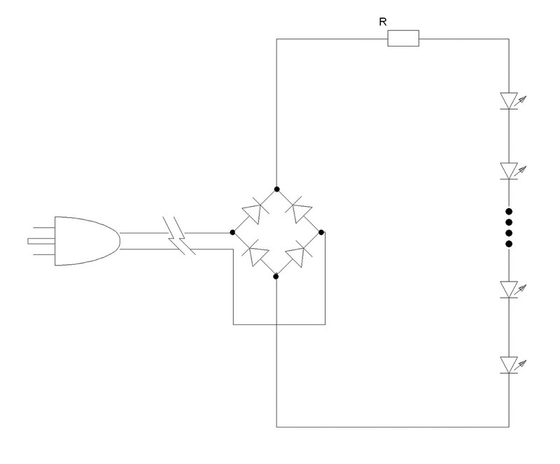
Figure 3:
The second generation of AC LED circuits
The third generation of AC LED circuits uses high voltage integrated circuits (ICs) to short out some of the LEDs such that at any time the voltage of the LEDs in the circuit is roughly comparable to the power line voltage. A current limiter in the IC serves to keep the current constant between switching operations. The third generation of AC LED circuits is shown in figure 4.

Figure 4: The third generation of AC LED circuits
In the third generation of AC LED circuits, the LEDs shown are typically high voltage LEDs now manufactured by numerous companies. Internally they contain multiple junctions so that the forward voltage might be around 30 V. Instead of the resistor shown, an electronic current limiter may be provided as part of the switch chip. The light output waveform from such a product is shown in figure 5.

Figure 5: Waveform of the light output from a third generation AC LED circuit
The efficiency of such a circuit is typically about 80%, the flicker index 0.32 and the power factor 0.98. The power factor is extremely high since no energy storage is present and the current is drawn from the power line exactly in phase with the power line voltage waveform. The useful property of such circuits is that the current limiter can be externally adjustable so that the products can be dimmed. If the application requires dimming this is clearly an advantageous circuit.
Introducing The Fourth Generation of AC LED Circuits
Many applications do not need dimming. When this is the case, it is possible to improve the efficiency from say 80% to 90%, and decrease the flicker index while reducing the cost through the elimination of the expensive high voltage integrated circuit switch chip. The principle used is to put two current pulses through the LED string per line voltage half cycle - the first a capacitively limited (displacement) current and the second a resistively limited (galvanic) current. By storing a small amount of energy on each half cycle for use on the next half cycle, the two pulses can be evenly spaced so that the ripple in the output current is to a great extent at four times the power line frequency. The best way to accomplish this depends upon the power level. This is because in the USA, Energy Star has no requirement on power factor for lights of less than 5 W. Only a few years ago, this might have corresponded to relatively dim lights; however, with steadily increasing LED efficacy, 600 lm can be produced today. Similarly, a 5 W, 900 lm light can be foreseen in a few years. To distinguish them from the conventional AC LED light engines, these products are referred to as “Driverless AC LED light engines.”
A circuit for a driverless AC light engine of under 5 W is shown in figure 6.

Figure 6: A driverless AC LED light engine circuit for under 5 W
This deceptively simple and very inexpensive circuit produces an output total LED current waveform with a flicker index of only 0.03. The vital waveforms representing operation of the circuit are shown in figure 7. The efficiency is just over 90% and the power factor is 0.45. In this case, poor power factor in return
for high efficiency and excellent quality of light is an acceptable compromise
being as there is no power factor requirement for consumer products under 5 W
in Energy Star.

Figure 7: Important operating waveforms for the under 5W driverless AC LED light engine
To understand how this circuit works, consider the first current pulse through the top string. This pulse starts at the positive peak of the incoming power line voltage waveform (With respect to the right side of the bridge rectifier, which for reference is used as common). At this point current is passing through R1, through the two strings of LEDs and R2, hence back to the bridge rectifier. This phase of the operation stops after about a millisecond, and then the falling power line voltage conveyed through C1 starts to pull charge out of C2 (charged in a previous half cycle) and then increasingly out of C4. When C4 is finally discharged there is a very abrupt fall in LED current, which is stopped by galvanic current starting to pass through the whole LED string as the power line voltage waveform approaches the negative voltage peak. All the capacitors used are smd ceramic capacitors of 2.2 uF or less and of 250 V rating, which are both small and inexpensive. During the beginning of the next power line half cycle, C4 and C2 are recharged.
It can be seen that C1 acts like a charge pump capacitor, alternately pulling current
out of the top half of the LED string and pushing it back into the bottom half.
Because of the presence of C2 and C3, about half of the LED current does
not go through the resistors at all, which is why the efficiency is over 90%.
The efficiency, input power and output current of a prototype design are
shown in figure 8.

Figure 8: Input and output currents of a prototype under 5 W driverless LED light engine
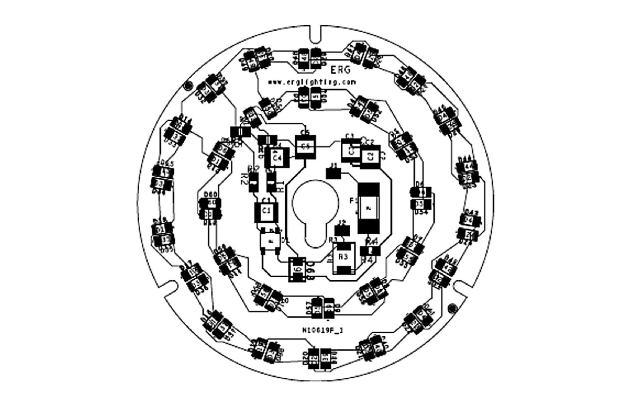
A picture of a complete under 5 W driverless LED light engine is shown in figure 9.
This example includes a fuse, and surge voltage protection as required for long life on the public power grid.
Since the light is produced alternately by the upper and lower strings of LEDs,
a feature of the design is the way that each LED from the upper string is located close against a corresponding LED from the lower string, so that the combination of the two produces light continuously. This ensures that no flicker can be perceived from the complete light engine, even though individual elements of the array are only activated at a frequency of 60 Hz (in the USA).

Figure 9: Example of a sub 5 W driverless LED light engine
As already mentioned, the flicker index of this product is 0.03. This compares with 0.32 for the best IC controlled AC driven light engines available today, or 0.15 for an incandescent light bulb. The efficiency is just over 90%, compared to 80% for most IC controlled AC driven light engines available today. The cost is lower because no expensive high voltage IC is needed to control it. This design is ideal for low cost non- dimming applications at the under 5 W power level.
A Driverless AC Light Engine Solution for
5 W and Up
At power levels over 5 W, Energy Star rules in the USA require a power factor in excess of 0.7. A circuit to meet these requirements is shown in figure 10.
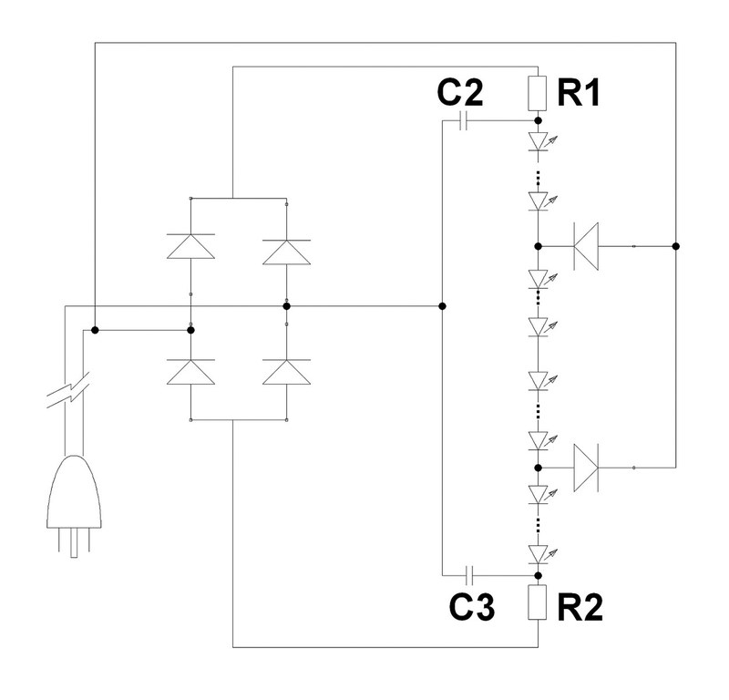
Figure 10:
A driverless AC LED light engine for power levels above 5 W with power factor > 0.7
The important operating waveforms for one of these circuits operating at a power level of 12 W are shown in figure 11.

Figure 11: Important operating waveforms for a 12 W driverless
LED light engine
This circuit is in some respects analogous in its operation to the previous one.
The LED strings are now subdivided into four equal sub segments. During positive half cycles the top sub segment is shorted out, and during negative half cycles the bottom sub segment is shorted out. When the input voltage starts to turn positive, C2 starts to charge up through R1, while simultaneously C3, which was previously charged to the negative peak of the line voltage, is receiving current passing through the lower three strings. This produces the first hump in the total LED current waveform characteristic of displacement current. When C3 is charged sufficiently to get to zero volts, then galvanic current starts passing through R2 instead, and this causes the second hump in the total LED current waveform. An exactly complementary series of charging and discharging events happens during negative half cycles. C3 gets discharged to a negative voltage equal to the negative line voltage peak. This is the reason why at the beginning of the positive half cycle the LED current starts immediately as the line voltage turns positive, giving such a short duration between the current pulses.

Figure 12: Main performance characteristics of a 12 W driverless
LED light engine
The main performance characteristics of one of these circuits operating at a
power level of 12 W are shown in figure 12. The flicker index of the output current waveform is 0.29, lower than is achievable by the best performing light engines using high voltage switching chips, which have a flicker index of 0.32. The efficiency is 87.5%, compared to the 80% or so characteristic of today’s AC LED light engines. The power factor is 0.72, sufficient to meet Energy Star requirements for consumer products in the USA.
At a power level of 12 W, capacitors C2 and C3 are 2.0 uF / 250 V, a convenient size for surface mount assemblies. Obviously much larger light engines can be produced this way, and surface mount capacitors can be placed in parallel to facilitate higher power levels.
Conclusions
From the two products that have been described above, it can be predicted that simple, non dimming LED drivers may become less common in the future, because the LED arrays themselves can so easily be arranged to be driverless AC LED light engines which run directly off the AC power lines with lower cost, higher efficiency and adequate power factor. These simple, low cost circuits outperform the existing conventional AC LED products with higher efficiency and lower flicker index. The exceptions to this prediction may be the cases where for some optical reason the light source needs to be just one high power LED as opposed to an array of LEDs. Also dimming applications will likely continue to be engineered as they are at present. Although this option has not yet been explored, the high voltage LEDs now available from numerous manufacturers lend themselves well to these driverless AC LED light engines, as long as the forward voltages of the devices are engineered to meet the needs of the circuit.
