Additive Optics Design and Fabrication for Smart Lighting Systems and Tailored Project Solutions
Since its initial invention back in 2009, printed optics has come a long way in the lighting industry. Additive optics fabrication is a future proof methodology of rapid prototyping custom LED optics by means of digital manufacturing technologies. Marco de Visser, Luximprint’s Director of Marketing & Sales, breaks down the technology and explains how its features add value to the design and manufacture of smart lighting applications. From one of Luximprint’s preferred optical design partners Physionary, Ramon van der Hilst, Founder and Business Development Manager, and Suresh Christopher, inventor of the state-of-the-art “target-to-source” optics design software, explain the benefits of an optimized design process.
Additive Optics Fabrication encompasses a 3D printing technology utilized to produce custom optics directly from a CAD file. In sharp contrast to conventional subtractive processes of milling, turning, grinding and polishing, additive manufacturing creates parts by building them up with progressive computercontrolled deposition of material, in a process that resembles printing, but with multiple passes until the desired 3D shape is achieved. How this works in detail and how optimized design software minimizes effort, while providing outstanding results is demonstrated.
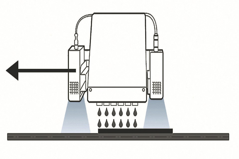
The Process at a Glance: Droplets on Demand
Additive optics fabrication services use digital UV-jetting technologies whereby transparent droplets of a UV-curable acrylic are jetted onto a given surface and then cured by strong UV-lamps. The results of the process are geometrical or freeform shapes that may include transparent prisms or lenses, both individual lenses or lens arrays.
Like in digital printing, the platform keep going until the “optical resin” - basically a container with a liquid acrylic - is empty, and the “paper” - a translucent substrate material like PMMA, Polycarbonate and glass - needs to be replenished. Even though the material is deposited in discrete drops, the resulting surfaces are smooth straight from the printer and don’t require post-processing.
Smooth and frosted finishes In addition to the smooth surface finishes, a defined surface roughness can be selected, for example, to generate a targeted scattering of light (spectral BSDF). Rough surfaces can be applied onto the optical part as a whole, or selectively applied onto the lenses or their connected surfaces, in one single process.
 of printed frosted finishes conforms international ISO 4287 standards. An 800 microns high pass filter was used") Figure 2: Surface roughness measurements (Ra / Rz in mμ) of printed frosted finishes conforms international ISO 4287 standards. An 800 microns high pass filter was used
Figure 2: Surface roughness measurements (Ra / Rz in mμ) of printed frosted finishes conforms international ISO 4287 standards. An 800 microns high pass filter was used
From Overstock to Novel Lens Design
One interesting feature arising directly from the additive optics fabrication process is replacement of the sheet material by any given lens object. As such, any existing lens module can be “reworked” into a new design by just adding some novel lens features to it. Painful tooling errors, such as unexpected blinding or aberration effects, can be compensated and tested before excessive tooling re-investments or costly tooling iterations are done.
The lens modules to be used may include a diversity of bolder lens types such as TIR lenses or lens arrays, or generally flatter sheet materials such as prismatic and light guiding plates, among others.
 Figure 3: Existing lens bases, such as TIR lenses, can be upgraded with novel lens design features to optimize or adjust the lighting system performance
Sheet materials - or individual lens objects - can be treated on both the top and bottom surface, as long as they are flat, using the dual sided printing methodology of the process.
 Figure 4: Explanation of dual sided lens with sheet printing methodology
This capability opens up an interesting space in the lighting market to tailor lighting system performance, take away unforeseen (glare) effects or customize the aesthetics in a way that was not available before. Apart from the time and cost savings that can be realized during the early development stages, the ecological and economic benefits of re-using obsolete stock or standard “off-theshelf” lens materials are of significant meaning to the industry.
Technology Meets Application
When it comes to its relevance for the lighting industry, we can break down additive optics fabrication into some main product areas of interest.
Printed optics
Lighting fixtures typically incorporate one or more secondary or tertiary plastic optics. They may consist of lenses, total internal reflection (TIR) optics, and diffusers that concentrate the light, magnify its intensity, guide it to a given target surface, and then finally blur it to enhance beam and color uniformity.
 Figure 5: Printed gradient array of micro lenses
Printed reflectors
Based on the smooth surfaces manufacturing capability, another interesting type of secondary optics can be produced: Reflective surfaces. Deposition of aluminum coatings or other types of reflective finishes onto the surface turns the smooth (high polish) or textured (matte) surfaces into a fully functional reflector item, from where functional testing of new systems can be done rapidly.
 Figure 6: Smoothness straight from the printer is key for reflective optical quality surfaces
Printed diffusers
Printed diffusers aim for a uniform light distribution and a comfortable light appearance. They provide an undefined or defined scattering of light aiming for better light control, reflectivity, source hiding, efficiency and finally, aesthetics. Thanks to the accurate droplet placement, a high level of customization can be achieved.
 Figure 7: Defined Frosted Finishes for antiglare and enhanced light control, nearing common industry standards for mold roughness
Printed molds and tools
Elaborating on the smooth optical quality surfaces to another extreme ends up in rapid fabrication of mold tools. Printing the lens “negative” rather than the positive, enables users to take immediate benefit of the smoothness, also for other purposes than diffractive or reflective optics.
In addition, lens positives are used for making “imprints” into secondary materials, such as ceramics or clay specialties, enabling rapid creation of soft manufacturing tooling for other material types. From this perspective, it is easy to replace optical materials or even non-optical materials, and from cool / UV curing resins to hot melt materials.
 Figure 8: In addition to optical quality parts, imprints of part positives enable rapid material replacement for other lighting system components, such as metals
Optographix
In addition to the optical lens parts for the engineering community, the additive printing approach gives the creative lighting design space access to the color features of the manufacturing process. A unique combination of “optics” and “graphics”, including either translucent “colored textures” or “color lenses”, in mono-color or multi-color, greatly enrich the ambiance of a given space or surface.
 Figure 9: Example of a green color filter integrated into one single prism lens part
Fortunately, there are also some very interesting developments underway that enrich today’s optics and system design landscape. Where additive optics fabrication technology breaks down the barriers of manufacture and addresses the “pain points” in today’s lens fabrication processes, conventional optics design software still needs a high level of expertise and time to get to a solution, mainly a compromise between the design software and the fabrication process.
The answer to overcoming the bottlenecks in conventional optics design methodologies is to apply modern mathematical methods from physics and computer programming to generate the required optics, leading the focus away from how to achieve it towards where the light is desired.
Complexity is for Free
Traditionally, the staple of optical design has been ray-tracing, combined with human expertise to optimize parameters of the design. This approach often entails manually finding the best optical design for a certain problem, relying on the expert’s insight to foresee the direction in which the optimal solution can be found. This reliance on expertise and foresight is not a coincidence! Rather, it is a consequence of the ray-tracing method utilized in most optics design programs.
![Figures 10 a&b: Diagram Ray-tracing method [Light source (ray file)] [Secondary optics (CAD)] [External distribution of light (Eulumdat)] (a). Target-to-source method [Light source (ray file)] [Secondary optics (CAD)] [External distribution of light (Eulumdat)] (b)](https://www.led-professional.com/media/resources-1_articles_additive-optics-design-and-fabrication-for-smart-lighting-systems-and-tailored-project-solutions_figure-10_cmyk.jpg/@@images/image-1280-4d922b83505acbc7784a5e7cfc0e5a26.jpeg "Figures 10 a&b: Diagram Ray-tracing method [Light source (ray file)] [Secondary optics (CAD)] [External distribution of light (Eulumdat)] (a). Target-to-source method [Light source (ray file)] [Secondary optics (CAD)] [External distribution of light (Eulumdat)] (b)") Figures 10 a&b: Diagram Ray-tracing method [Light source (ray file)] --> [Secondary optics (CAD)] --> [External distribution of light (Eulumdat)] (a). Target-to-source method [Light source (ray file)] --> [Secondary optics (CAD)] --> [External distribution of light (Eulumdat)] (b)
Figures 10 a&b: Diagram Ray-tracing method [Light source (ray file)] --> [Secondary optics (CAD)] --> [External distribution of light (Eulumdat)] (a). Target-to-source method [Light source (ray file)] --> [Secondary optics (CAD)] --> [External distribution of light (Eulumdat)] (b)
While the ray-tracing method is very reliable, it works in a straightforward manner. It begins at the light source in order to arrive at the target: the external distribution of light often stored as a Eulumdat file or a ray-file. The optical design here is “input”, whereas the target distribution is “output”. An important consequence of this source-totarget method is that a complex target distribution requires the optical designer to input an optical design with similar complexity in order to control the light well. One can imagine that this becomes arduous if a large amount of complexity is required.
Applying the target-to-source method of calculating optical design, in this case, the output is the optical design in a digital format, whereas the inputs are the light source properties and the requested external distribution of light. While there is a mathematically infinite set of optical solutions that provide the requested distribution given the light source, modern optimization algorithms can cut through the proverbial fog to provide the most practical designs. An important consequence of this method is that at least the same level of complexity is transferred from the requested distribution of light to the optical design.
Image faceted lens
The first application of this technology is through the programmatic generation of faceted lens designs. A faceted lens consists of many similar-sized facets that “cut up” the light from the source. Each facet then aims the narrow bundle of light passing through it in a specific direction, such that all the beams from all the facets together make the requested external distribution of light. It does not matter whether that goal is a simple spotlight, or two spotlights, or something as complex as a logo. The complexity of the optical design stays the same, and often a single optical element is enough.
 Figure 11: With additive optics design and fabrication, complexity is “free”: designing and printing a complicated lens is no more difficult than a basic one - “Sunflower Fresnel”, a multi-facet lens precisely directing light to the illumination target
Image bundles from a faceted lens
A lens of 50 mm diameter with 4 mm² facets has approximately 500 facets. If an LED with a light emitting surface length of 2.4 mm is placed 25 mm behind the lens, each of the 500 beams has a (FWHM) opening angle of 5-10°. This spread in opening angles can be used to optimize the distribution of light, or eliminated by changing the relative size of the facets. The beams could be made even narrower by using a smaller LED at a larger distance with a practical limit of about 2°, though placing the LED closer to the lens also reduces the size of the outer beams while at the same time increasing the size of the middle beams. The preferable method depends on the application.
One advantage of having a relatively large lens surface is that it is possible to reduce glare. Depending on the target distribution, facets on different areas of the lens can aim in similar directions. For someone looking into the light, the LED’s sharp point of light is now spread over multiple points in different areas of the lens. This has the added benefit that it reduces the sensitivity to fouling by environmental effects, and redundancy in the case of partial obstruction.
 Figure 12: Lens bundles from facetted lens form light typography
The target-to-source method is ideally suited to give the creativity back to the light architects, artists, and designers by providing reliable optical designs with proven quality, while being able to deliver unique designs for every assignment. Using additive manufacturing, every lighting project has access to optimized optical designs of the level of complexity needed.
Additive optics manufacturing combined with target-to-source optical design methods open up a world of opportunities for creative lighting designers in branches as diverse as public lighting, artistry, architectural lighting, art illumination, and advertising. Because the efficiency of single element optics is naturally high compared to most other methods of beam-shaping, e.g. image projection methods and shutters, it is our expectation that faceted lenses and other target-tosource based optical designs will become the norm for the creative lighting industry.
Optics Design Meets 3D Printing Technology
New opportunities in custom optics design and development arise for the lighting industry when “smart optics design” and “additive optics fabrication” get together. A combination of, for example, Luximprint and Physionary services, is extremely powerful, as the intelligent piece of design software incorporates and considers the optical 3D printing platform capabilities when generating designs for manufacture. Product developers, on the one hand, can now benefit from the ‘printing-on-demand’ of custom designed LED optics, with no costly commitments to tooling and inventory, while creative lighting specifiers can get uncompromised lighting solutions, meeting the exact quantities and needs for their custom project. All in just a matter of days.
References:
[1] Luximprint - Additive Optics Fabrication Services for inspirational, decorative and functional optical plastics www.luximprint.com
[2] Physionary - Revolutionary Target-Source Optics Design SW for custom Optics - www.physionary.nl
