Advanced Passive Thermal Management Solutions for High Power LEDs by Advanced Cooling Technologies (ACT)
There are two main solutions to improve passive thermal management in LED devices. One is to increase the surface area of a heat sink. This requires additional size, weight and material and offers only marginal improvement. The second solution is to increase the thermal conductivity between the heat source and the sink. The latter is supported by well-established technologies like heat pipes and vapor chambers. Richard Bonner, Manager for Custom Products, and Peter Ritt, Vice President at Advanced Cooling Technologies (ACT) give insight into the latest developments and explain how they work, how they are designed and applied correctly, and discuss their opportunities, advantages and limitations.
There are two main solutions to improve passive thermal management in LED devices. One is to increase the surface area of a heat sink. This requires additional size, weight and material and offers only marginal improvement. The second solution is to increase the thermal conductivity between the heat source and the sink. The latter is supported by well-established technologies like heat pipes and vapor chambers. Richard Bonner, manage for custom products, and Peter Ritt, vice president at Advanced Cooling Technologies (ACT) gives insight in the latest developments and explain how they work, how they are designed and applied correctly, and discuss their opportunities, advantages and limitations.
Heat Pipe Fundamentals
The most typical form factor for a heat pipe is a copper walled tube of 3 to 8 mm in outer diameter. The lengths are highly customizable, but most applications require 4” to 10” long heat pipes. Inside the tube is a wick structure and a small amount of a working fluid. Most LED applications require copper tubes with copper wicks and have water as the working fluid. However, there are several other envelope materials, wick structures and working fluid combinations for a typical temperature range requirements. A heat pipe transfers heat by circulating the working fluid whenever a temperature gradient is applied, as shown in figure 1. The temperature gradient in LED applications is generally created by the waste heat generated by the LED’s in conjunction with a heat sink exposed to ambient air. The applied heat evaporates liquid out of the heat pipe’s wick structure. The vapor exiting the evaporator wick is swept to the cold condenser where it condenses back into the wick structure. The wick structure continuously returns the condensing liquid to the evaporator through capillary pressure.
 Figure 1: Heat pipe operation
Although heat pipes can appear simple and elegant, many design options must be considered when implementing heat pipes in practical applications. The correct wick structure is key to maximizing performance. The wick’s pore size, permeability, and thickness need to be tailored in order to maximize the amount of power that can be transferred. A classical trade off exists between capillary pressure generated by the wick (which increases with decreasing pore size) and liquid permeability (which decreases with decreasing pore size). In preliminary design stages convenient heat pipe calculators capturing these physics can be used to assess feasibility [6].
Fluid inventory control is an important design and processing parameter. Excess fluid can create flooding conditions within the heat pipe which negatively impacts the thermal resistance of the heat pipe. Fluid inventory is also key to enabling freeze thaw capabilities within heat pipes. Finally, insufficient fluid can cause premature dry-out.
It’s important to note that heat pipes can operate against gravity, with the evaporator located above the condenser. Typically, heat pipes can transfer heat as much as ~8” against gravity with a properly designed wick structure, although operating in reflux mode (evaporator below condenser) is preferred. In terms of heat flux capabilities, typical copper water heat pipes can operate with heat fluxes up to 50-75 W/cm2. Additionally, heat pipes can be bent and flattened to fit countless geometric shapes.
Heat Sink Performance and Weight Improvement
In some LED lighting applications, such as high bay lighting, large extrusion or cast aluminum heat sinks are used to dissipate heat to ambient air. Placing a discreet heat source on a large metal heat sink will produce large thermal gradients between the heat source and outermost located fins. Embedding heat pipes in the heat sink can increase the thermal conductivity from around 200 W/m·K (for extruded aluminum, even lower for casting alloys) to between 500 and 1,200 W/m·K. Designers can use this increase in thermal performance to reduce the weight or increase the power density of their lighting system. This approach can be implemented in a variety of LED applications including large arrays, outdoor lighting as well as some down lighting applications.
 is 12” long, with a base thickness of 0.6”, and weight of 9.6 lbs. The Hi-K heat sink (right) is 10” long, with a 0.28” base, and weighs only 6.3 lbs") Figure 2: Comparison of aluminum heat sinks. Heat sink (left) is 12” long, with a base thickness of 0.6”, and weight of 9.6 lbs. The Hi-K heat sink (right) is 10” long, with a 0.28” base, and weighs only 6.3 lbs
Figure 2: Comparison of aluminum heat sinks. Heat sink (left) is 12” long, with a base thickness of 0.6”, and weight of 9.6 lbs. The Hi-K heat sink (right) is 10” long, with a 0.28” base, and weighs only 6.3 lbs
Figure 2 shows a schematic of similar performing heat sinks with and without heat pipes. The conventional metal heat sink is 12” long, weighs 9.6 lbs and has a base thickness of 6/10 of an inch. Introduction of 5 heat pipes, 3 in close proximity to the heat source and another two a little further out for heat spreading, reduces the overall length to 10 inches, and the weight can be reduced to 6.3 lbs. an overall material reduction of nearly 35%. Figure 3 shows a result taken with an IR camera on both of these heat sinks when 150 W of thermal power is applied to each heat sink.
 and 35% smaller Hi-K heat sink (right). Result shown was acquired using an infrared camera") Figure 3: Comparison of test results for standard size aluminum extrusion heat sink (left) and 35% smaller Hi-K heat sink (right). Result shown was acquired using an infrared camera
Figure 3: Comparison of test results for standard size aluminum extrusion heat sink (left) and 35% smaller Hi-K heat sink (right). Result shown was acquired using an infrared camera
High Performance Heat Spreading
In a growing number of high power LED applications, such as UV curing devices, overall thermal performance is limited by the ability to quickly spread heat from the high power density sources. These products typically operate at high power, requiring dissipation of hundreds or even thousands of watts, but must maintain tight temperature range so that the output optical wavelength remains constant. The problem is further aggravated because an additional thermal interface layer is needed between the heat source, typically made of some low thermal expansion semiconductor material, and heat dissipating device, such as copper or aluminum, which have much higher coefficient of thermal expansions (CTEs). Typical compliant interface materials include thermal gap pads and thermal pastes. Without such a compliant thermal interface layer, the different materials’ coefficient of expansions will result in the heat source device cracking or severing from the heat dissipating device. Unfortunately the presence of this thermal interface layer increases the thermal resistance and likewise increases the temperature on the LED device itself.
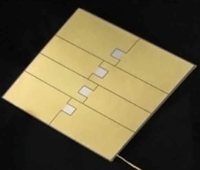
With both heat pipes and vapor chambers, it is most advantageous to have water as the working fluid, for both cost and performance reasons. Copper has been shown to have excellent compatibility with water, but copper has a relatively high CTE and would be thermally mismatched with common high heat load LED devices and would require a compliant thermal interface layer. Additionally, conventional wick structures have limited performance capabilities, which may not always satisfy performance requirements for high heat load devices. The desired solution is to have a water compatible vapor chamber, that is CTE matched to eliminate low performing compliant thermal interfaces in favor of a higher performing (albeit rigid) solder attachment process [7-8]. Such a heat pipe device is available and has been called the low CTE vapor chamber. The CTE matching feature allows semiconductor based LED’s to be directly attached to the heat spreader using solder, which is about an order of magnitude better than compliant thermal interfaces.
 Figure 4: Low coefficient of thermal expansion vapor chamber that allows direct solder attachement of LED devices
Additionally, unique high performance wick structures located at the heat source further improve overall thermal performance. There is a combination of very thin and very thick wick material co-located here. The thick wick is constantly collecting the condensate returning the cooler condenser portion of the vapor chamber and is delivering liquid to the thin wick area. The thin wick can quickly evaporate the fluid achieving very low thermal resistant values. Examples of the thick/thin wick structure can be seen at the bottom of the page with the Lateral Liquid Delivery. This structure has been shown to have a very high CHF critical heat flux, with an evaporator resistance of only 0.05 K·cm2/W.
 Figure 5: Advanced vapor chamber wick structures capable of dissipating greater than 500 W/cm2 heat fluxes at 0.05 Kcm2/W thermal resistances
Conclusions
Specialized LED lighting applications are more commonly requiring thermal management capabilities beyond traditional aluminum heat sinks. When done properly, heat pipes can silently and passively improve thermal performance, limit heat sink size, and increase reliability in LED applications. In many cases, heat pipes can be used to significantly reduce the size and improve the performance of aluminum heat sinks with simple integration strategies. In ultra-high performance applications, advanced heat pipes and vapor chambers can be used to enable the maximum performance using state of the art wick structures and materials that allow for superior thermal interface performance.
References:
[1] Zhang, J., et al., “Research Progress on Packaging Thermal Management Techniques of High Power LED”, Advanced Materials Research Vols. 347-353 (2012) pg 3989-3994
[2] Horng, R. H., et al., “Optimized Thermal Management From a Chip to a Heat Sink for High-Power GaN-Based Light- Emitting Diodes”, IEEE Trans on Electron Devices, Vol. 57, No. 9, Sep., 2010
[3] Christensen, A., et al., “Thermal effects in packaging high power light emitting diode arrays”, Applied Thermal Engineering 29 (2009) 364–371
[4] Fan, A., Bonner, R., “An Innovative Passive Cooling Method for High Performance Light-emitting Diodes”, Semitherm 2012, San Jose Ca, March 2012
[5] Pounds, D., Bonner, R., “High Heat Flux Heat Pipes Embedded in Metal Core Printed Circuit Boards for LED Thermal Management”, 2014 IEEE Intersociety Conference on Thermal and Thermomechanical Phenomena in Electronic Systems (ITherm), Orlando, FL, May 27-30, 2014
[6] http://www.1-act.com/resources/heat-pipe-calculator/
[7] Dussinger, P., Sungtaek Ju, Y., “High Heat Flux, High Power, Low Resistance, Low CTE Two-Phase Thermal Ground Planes for Direct Die Attach Applications:, GOMACTech 2012, Las Vegas, NV, March 2012
[8] Luo, Xiaobing, et al., “Low thermal resistance LED light source with vapor chamber coupled fin heat sink”, Proceedings of 60th IEEE Electronic Components and Technology Conference (ECTC), 2010
