Challenges when Designing LED-Based Illumination Systems in Medical Applications and Diagnostics
LEDs have become indispensable in medical technology and dentistry. But the requirements placed on these lighting products are very high: Minimized size, high, application specific color rendering index, efficient temperature management, usability and excellent disinfection opportunities are all extremely important. Prof. Paola Belloni from the Steinbeis Transfer Center Illumination Optics and Lighting Engineering and Furtwangen University, and Alexander Gärtner from the Faculty of Mechanical and Medical Engineering of the Furtwangen University discuss the requirements for different applications such as endoscopy, surgeries, dental devices, and photodynamic therapy. Further topics are the development of a self-disinfecting operation interface with edge-lit UV-A LEDs, and a new optimization approach, taking into account the reflection and absorption properties of human tissues.
An increased demand for minimally invasive treatments and a better understanding of photobiology has led to a growing interest in LED-based therapies. The clinical applications of red, yellow, blue, UV and near infrared (IR) LEDs include wound healing, acne treatment, sunburn prevention, phototherapy for facial rhytides, and skin rejuvenation [1]. All these LED-based therapies rely on the principle that electromagnetic radiation of different wavelengths triggers the healing process by means of the biological effects of radiation on the human body. Below we report on a recently started project of a photobiomodulation treatment in which an LED-based device will be designed for in-vitro wound healing applications.
However, hereafter, this article focusses on the development challenges of LED-based medical devices. The development is driven by the requirement of adequate in-situ illumination for correct positioning and operation of the medical device. Traditionally xenon, halogen and metal halide lamps have been used as surgical light sources because of their high luminance and color rendering index (Ra ≥ 95). These lamps emit over a broad spectrum across the visible range and can provide a colour close to daylight. Usually, the incorporation of various filters in order to attenuate unwanted wavelengths directly in front of the light source is required. However, a conventional lighting environment produces a lot of heat leading to the waste of energy and a short lifetime.
Currently, LEDs are systematically replacing Xenon lamps in medical devices because they are energy-efficient, small, durable, less expensive and their spectral emission in the visible range can be tuned. In fact, a natural color reproduction of the tissue or the tissue contrast is becoming more important for medical diagnostics. Optical properties of biological tissue vary widely depending on the tissue type that may be highly reflective (fat), highly absorptive of blue/green light (blood) or may have fluorescent properties (collagen) [2]. Therefore, using LEDs as light sources allows developing multifunctional illumination units which spectral characteristics can be flexibly adapted to the specific diagnostic procedures.
Spectrally Tuned Illumination Units for Color and Contrast Enhancement
In medicine recognition of red color is essential for diagnosis and surgical treatment. There is a general agreement that standard lamps used during medical procedures have to meet the requirements of high values of general colour rendering index (Ra) and specific colour rendering index for sample 9 (R9) exceeding 92.
Moreover, in photodynamic diagnosis blue light is used for excitation of fluorophores to aid visualization of tumours [3] whereas narrowband imaging with helps to increase tissue contrast and therefore the visibility of the vasculature [4]. The spectral output of multileds sources may be tuned to any colour in a triangular region of the chromaticity diagram CIE and includes white light of varying colour temperature and can be adjusted to match a number of standard illuminants including daylight and Xenon. When used with a white-balanced video camera the output of this multileds source provided white light at a similar imaging quality to the standard Xenon sources (Clancy et al [5]).
A description of tuneable LED-based light sources optimized for color and contrast enhancement of tissues as well as validated in medical diagnostics follow.
Clancy et al. [5] described an homogenized LED light source made up of four ultrabright LEDs in the red, green, blue and violet (λ < 430 nm) spectral regions. A light pipe multiplexer combines light from each of the four LEDs and couple it efficiently into the optical fibre bundle using dielectric thin-film optical coatings. The LED light source is coupled to a standard endoscope and color contrast on ex vivo tissues analised.
Blaszczak et al. [6] constructed a tuneable LED-based multi-emitter source made up out of 13 LEDs which allowed adjusting the correlated colour temperature. Correlated colour temperature of this LED set can vary from 2700 K to 6500 K and the colour rendering indexes are not lower than 93 (Ra>97 R9>98, R1-R14>93). Different shapes and sizes of mixing optical elements were first calculated and then verified with a prototype to optimise the quality of colour mixing.
A commercial device recently available [7] has focussed on providing high contrast in the tissues by shifting the spectral properties of the LED sources (Figure 1).
 enables a direct comparison of tissue structures on the monitor during surgery and thus facilitates the diagnosis") Figure 1: The simultaneous display of a white light image and an image in the visualization mode (Chroma, Spectra) enables a direct comparison of tissue structures on the monitor during surgery and thus facilitates the diagnosis
Figure 1: The simultaneous display of a white light image and an image in the visualization mode (Chroma, Spectra) enables a direct comparison of tissue structures on the monitor during surgery and thus facilitates the diagnosis
In the Spectra mode of the Video-Uretero-Renoscope FLEX-Xc of Karl Storz, the bright red portions of the visible spectrum are filtered out and the remaining color portions are expanded to allow recognition of the finest tissues. Additionally, the Chroma mode intensifies the color contrast in the image. Clearly visible structure surfaces are emphasised while retaining the color perception in the image.
LED-Based Endoscopy: State of the Art and Innovative Future Solutions
Endoscopic surgery has become an extremely significant process in today’s medical diagnostic and therapy. The internal organs in the human body form a plurality of inner surfaces which can be investigated with the aid of an endoscope. Most lesions such as cancer or altered blood vessels start from the epithelial tissue which lies on the surface of the organs [2].
Even nowadays, most endoscopic video processors in clinical use still have Xenon lamps as cold light sources.
LED-based endoscopic illumination devices have been shown to have several benefits over the traditionally used Xenon lamp systems. However, their use in endoscopy has been initially limited by the difficulty to couple enough light into the endoscopic light cable efficiently. In fact, light from a source with a large angular Lambertian intensity profile must be matched to the small numerical aperture of a light guide or fibre bundle. The coupling efficiency can be significantly improved by a collimating lens inserted between the LED and the fiber end [8].
Up to now, the actual light source is outside the endoscope in an external unit. The light is transported by means of total reflection through a fibre-optics cable to the endoscope end. This leads of course to a cumbersome handling of the medical device. Therefore, it would be a much better solution to integrate the LED light source into the endoscope itself, by placing it either in its handle or its tip.
Both technical possibilities present challenges with respect to heat dissipation in order to be compliant with the strict regulations regarding temperatures and electrical safety of medical equipment as defined in the European normative DIN EN 60601 [9].
When mounting LEDs in the handle, the generated light has to be transported to the surgical field via fibre optics. As already mentioned above, additional optical components are necessary to avoid substantial losses when coupling LED light into fiber optics. Unfortunately, the spacial constraints imposed by the handle geometry are less favourable than those in an external light box. Recently KARL STORZ introduced an Uretero-Renoscope with LEDs integrated in the handle [7].
When integrating LEDs into the tip of the endoscope, the entire luminous flux is available for illumination of the surgical site. However, it is necessary to transfer heat to the endoscope’s handle in order to avoid overheating of the tip. Its minute size does not support thermal dissipation towards the surroundings. Moreover, DIN EN 60601 requires lower maximum temperatures for metallical device components that become in contact with human tissues compared to components that do not.
Brügemann [10] analysed the LED-integration on the endoscope tip and proposed to incorporate heat pipes to avoid overheating. Measurements of his prototype looked promising and proved compliant with DIN EN 60601.
The future of LED based endoscopy seems to be bright, but yet serious research efforts needs to be focused on improving the light coupling between reflected light from inspecting tissue and CCD of the camera, the electrical to light power conversion efficiency and the homogeneity of the illumination.
EDISON- Project
Endoscopy Illumination System Endoscopy Illumination System Optimization (EDISON) is one of the ten new projects in the research frame work initiative CoHMed (Connected Health in Medical Mountains) aimed at transferring current scientific trends in medical technology to biologize, miniaturize, and digitalize medical devices with industrial partners of the University of Furtwangen. EDISON´s main goal is to improve light guides in rigid endoscopes by increasing the efficiency of the illumination unit and the uniformity of the illuminated area. First, the spectral properties and angular distribution of LED light sources and fibre optics are optically simulated with LightTools (Synopsys©). Those findings will be experimentally validated with measurements of prototypes in the lighting laboratory (Figure 2).
 Figure 2: Schematic description of the development process. A rigid endoscope with critical spots for radiation losses, the equipment of the lighting laboratory used during the analysis of the light source and endoscopic device, example of optical simulations
Moreover, critical issues in the light transport and coupling inside the endoscope device itself will be identified:
- Shape and dimension of the coupling interface (i.e. glass condensing cone)
- Entrance and exit angles of light at the interfaces (α,β)
- Dispersive losses in the fibers optics and in all other optical components
Optimization results will be systematically fed back into the development process, resulting in new prototypes with improved light guides and coupling units.
Measurements of the typical efficiency of state of the art rigid endoscopes powered by LED light sources - defined as a ratio between luminous flux out of the endoscope relative to the fiber optics one - confirmed a very low value of approximatly 35 %. The first optical simulations clearly show that the glas condensing cone is crucial for light intensity losses and that the coupling efficiency is strongly dependent on the angular distribution of the fibre optics light input (Figure 3).
") Figure 3: Optical simulation of light coupling from a fiber bundle into the glass condensing cone of the endoscope. The receivers placed on the surface of the condensing cone show the regions in which most of the radiation losses occur (green color)
Figure 3: Optical simulation of light coupling from a fiber bundle into the glass condensing cone of the endoscope. The receivers placed on the surface of the condensing cone show the regions in which most of the radiation losses occur (green color)
A further EDISON goal is to develop a spectral composition for the LED-source that will offer the best specific contrast between the surgeon’s area of interest (tissue with suspicious pigmentation, appearance, texture, color, …) and surrounding tissues which can in a sense be considered as background (or normal). Therefore, the specific reflection properties of theses different areas have to be considered in the optimisation of the light source as only reflected light is usable for the surgeon. Systematic measurements of angle dependent reflection and transmission properties of representative human tissue samples are planned.
The advantage of a spectral reflectance comparison model has been shown by Shen et al. [11] and will be briefly described here. They focussed on searching for the wavelengths which produce the highest contrast between blood vessels and background tissues. An LED-based ceiling system made up of 11 high power LEDs, consisting itself of eight color LEDs and three white LEDs with different correlated color temperatures (CCTs) was used as light source. The intensity level of each LED could be controlled and software was developed to generate the target source spectral distribution.
The spectral reflectance contrast C(λ) is defined as
![]()
where Rm and Rb are the spectral reflectance spectra of blood and background tissue.
To verify the accuracy and stability of this method an ovine heart was set and imaged (Figures 4a-d). The C(λ) (Figure 4b), implies that the spectral components between 450 and 550 nm contribute the most to the identification of blood vessels that have a meat background.
 camera and before the experiments the camera and the PR655 SpectralScan spectrometer were all calibrated with the D65 standard light source. Spectral radiance of incident light (a). Spectral reflectance of fresh ovine blood obtained with a spectrometer (c). Spectral reflectance of ovine myocardium background tissue (d). Spectral reflectance contrast - C(λ) - of blood and background myocardium tissue (b). Tissues illuminated with wavelengths between 450 and 550 nm will have a strong gray contrast in the display image, which will help the surgeon easily identify them (from Clancy et al. [5])") Figures 4a-d: Images of specimens were obtained using a charge-coupled device (CCD) camera and before the experiments the camera and the PR655 SpectralScan spectrometer were all calibrated with the D65 standard light source. Spectral radiance of incident light (a). Spectral reflectance of fresh ovine blood obtained with a spectrometer (c). Spectral reflectance of ovine myocardium background tissue (d). Spectral reflectance contrast - C(λ) - of blood and background myocardium tissue (b). Tissues illuminated with wavelengths between 450 and 550 nm will have a strong gray contrast in the display image, which will help the surgeon easily identify them (from Clancy et al. [5])
Figures 4a-d: Images of specimens were obtained using a charge-coupled device (CCD) camera and before the experiments the camera and the PR655 SpectralScan spectrometer were all calibrated with the D65 standard light source. Spectral radiance of incident light (a). Spectral reflectance of fresh ovine blood obtained with a spectrometer (c). Spectral reflectance of ovine myocardium background tissue (d). Spectral reflectance contrast - C(λ) - of blood and background myocardium tissue (b). Tissues illuminated with wavelengths between 450 and 550 nm will have a strong gray contrast in the display image, which will help the surgeon easily identify them (from Clancy et al. [5])
The presented results showed that images obtained with an optimized spectrum had a higher contrast than those obtained with a commercial white light even if different color temperatures were used.
UVA-LED Applications
Recent improvements in flux density, stability and life hours of UV-LEDs have made them a viable solution for replacing traditional UV light sources such as mercury lamps, Xenon lamps, hot and cold cathode lamps. The applications vary from curing, counterfeit detection and digital printing (UVA), phototherapy (UVB) and disinfection/purification (UVC). Below we report on two optical development projects conducted with industrial partners over the last 3 years. The motivation was either to integrate UVA LEDs in existing products or to enable new applications previously not feasible with conventional UVA lamps. One of the main challenges was identifying suitable UVA LEDs among the very few reliable products which had the required power output and optomechanical characteristics. In the meantime the availaibilty of high power UVA LEDs, even in the deep UVA, has rapidly increased, since more companies have entered this market. Therefore we believe that most of the problems we faced could be now successfully solved.
Optical design of a self-disinfecting operation interface
Disinfection of surfaces is necessary in biological laboratories and medical facilities to reduce the risk of contamination or decease contagion. Bacteria and germs on the glass surface coated with TiO2 can be oxidized with sufficient UV exposure. Many studies suggest that the photocatalytical effect of TiO2 can be triggered with much longer and easier-achievable wavelengths, i.e. UVA, and with an overall lower intensity dosage, compared to the UVC-disinfection. The system can thus be strongly antimicrobial [12]. Based on this principle, we developed an active self-cleaning touch-system with a glass surface and several integrated UVA LEDs for applications like a nurse-on-call system. We used UV-LED light sources with a central wavelength of 375 nm, FWHM of 11 nm and 320 mW power output (Seoul Optodevice).
For the concrete product application, there were some boundary conditions:
- Minimum UVA intensity reaching the TiO2-coating greater than 3 mW/cm. (trigger threshold for free ions in the semiconductor)
- Continuous UVA irradiation covering the whole display area with sufficient homogeneity
- No additional cover/frame around the glass panel
- Light source invisible to user
Behind the glass panel there is a normal printed circuit board with several layers such as design, resin, copper and solder resist and none of these layers is UV-transparent. Therefore, as figure 5 shows, we constructed our system as a modified back-lighting model with the following components: Sideways-coupled light sources (hidden on the edge), a light guide, 3D extraction textures on the bottom of the light guide and a UVA reflective diffuser layer.
Figure 5 shows the glass panel and a thin TiO2 coating with a refractive index of 2.5 positioned directly on its top surface. Eight LEDs are coupled in, four on each short edge. The glass is defined as a whole body with a refractive index of 1.52 at 375 nm. The 3D extraction textures zone is located on the bottom side of the glass to improve the uniformity of light extraction. Additionally, a very thin UVA reflective film with a Lambertian distribution is placed directly below the 3D extraction textures to simulate the white coating of the electrical board beneath the touch screen and to increase light scattering.
 Figure 5: System of the described self-disinfecting operation interface showing the glass panel with the TiO2 coating
A prototype with 3D-laser extraction textures was produced and measured. The homogeneity of UVA irradiation distribution on the TiO2 coated surface matched the optical simulations, but the irradiance values were lower than predicted and less than the required photocatalytical threshold of 3 mW/cm.. The intensity losses were caused by the white coating, that was absorbing UVA. Therefore, we investigated different white coatings with higher reflectivity in the UVA range, but no satisfactory alternative was found.
Of course the critical threshold could have been reached using:
- More UVA-LEDs, increasing the costs of the self-disinfecting touch screen device
- LEDs in deeper UVA range, which were not yet available
Design and development of a light module for constant climate chambers
Climate chambers are used to test the effects of specified environmental conditions like extreme temperature, moisture or relative humidity, electromagnetic radiation, exposure to sun etc. on biological items and materials. In a constant climate chamber for photostability tests the light module has been traditionally equipped with fluorescent lamps to provide intensity and spectral distribution according to to the guideline ICH Q1B [13]. This guideline defines the photostability test conditions for new drugs and products by requiring exposure times of 1.2 Million lux hours in the visible and 200 Watt-hours/m. in UVA-range. Moreover, the guideline specifies the type of visible and UVA spectral light distribution to be used and on of the options allows the simultaneous exposure to a cool white fluorescent and a near ultraviolet lamp light.
The substitution of fluorescent lamps with LEDs presents some advantages:
- More space for test materials in the climate chamber due to smaller size of LEDs
- Less weight
- Longer lifetime of the light module
Therefore we started a feasibility study with the goal to design and develop a new opto-mechanical light module equipped only with LED light sources in both visible and UVA-range. The German company Binder [14] made available a climate chamber for photostability tests allowing us to test our development results in realistic conditions.
For the optical design and development of an LED-based light module for the climate chamber, we derived constraints on the LEDs spectral distribution, Power/Lumen package, Lifetime (ideally 50,000 hours for both visible and UVA components) and compatibility to both humidity (> 80%) and temperature conditions(up to 70°C).
In the visible range we used strips of low power LEDs (CCT = 6000 K) with lambertian angular distribution without secondary optics (870 lm per 500 mm LED strip). Only two UVA-LEDs were found to be acceptable despite not optimal electro-optical characteristics. The optical characteristics of the finally selected LED are a power output of 60 mW, a peak wavelength λp = 365 nm with a 20 nm FWHM, and a lifetime of only 10,000 hours (Seoul Optodevice). Its mechanical characteristics allowed it to be easily integrate into the circuit board.
The spatial distribution of UVA and cool white LEDs was optimised with respect to illuminance, irradiance and uniformity targets (Table 1) using the minimum amount of LEDs. To improve the uniformity of light extraction, we added 3D spherical extraction textures i.e.holes with a fixed radius of 0,5 mm to the front glas surface of the light module and calculated their best density.
 Table 1: Development requirements for the new light module. Illuminance/irradiance and uniformity values are given for a distance of 12 cm from the light sources. The uniformity values refer to the mean value on a 350x500 mm area, which represent the usable surface area of the climate chamber for materials tests
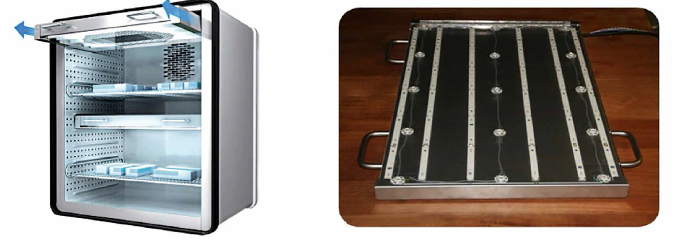
 for photostability tests of the company Binder showing a flexible positionable light module traditionally equipped with fluorescent lamp. The prototype (b) equipped with 15 UVA LEDs uniformly distributed (0.9 W) and 8 cool white LEDs strips horizontally and vertically distributed (6300 lm)") Figure 6a&b: Constant climate chamber (a) for photostability tests of the company Binder showing a flexible positionable light module traditionally equipped with fluorescent lamp. The prototype (b) equipped with 15 UVA LEDs uniformly distributed (0.9 W) and 8 cool white LEDs strips horizontally and vertically distributed (6300 lm)
Figure 6a&b: Constant climate chamber (a) for photostability tests of the company Binder showing a flexible positionable light module traditionally equipped with fluorescent lamp. The prototype (b) equipped with 15 UVA LEDs uniformly distributed (0.9 W) and 8 cool white LEDs strips horizontally and vertically distributed (6300 lm)
The prototype (Figure 6b) was designed and made to be compatible with the mechanical constraints of the climate chamber. The irradiance and illuminancevalues measured as well as their uniformity showed a very good agreement with the optical simulation results [15].
Despite the overall positive results, one issue must be further addressed. Due to their narrow band emission, the UVA-LEDs selected emit very little radiation below 355 nm. This can be seen as an argument against their use in climate chambers for photostability tests because the light sources must have a significant emission above 320 nm according to the current guideline ICH Q1B (Figures 7a&b). But in the meantime, some deep UVA LEDs in the range 320-350 nm have become available and could be additionally used in the light module to fill the irradiance gap below 355 nm. An additional major development constraint for a solely LED-based light module was the 10000 hours lifetime of the UVA LEDs. This is currently being improved, given the increased demand for long life UVA LEDs.
. Zoom of the UVA spectral range from 320 nm to 400 nm showing an emission peak between 350-370 nm but not enough radiation in the 320-360 nm region (b)") Figures 7a&b: Comparison between the spectral distribution of the new LED light module and the old one, showing overall a good agreement in the visible range (a). Zoom of the UVA spectral range from 320 nm to 400 nm showing an emission peak between 350-370 nm but not enough radiation in the 320-360 nm region (b)
Figures 7a&b: Comparison between the spectral distribution of the new LED light module and the old one, showing overall a good agreement in the visible range (a). Zoom of the UVA spectral range from 320 nm to 400 nm showing an emission peak between 350-370 nm but not enough radiation in the 320-360 nm region (b)
LED-Based lllumination Unit for Photobiomodulation in Vitro Studies for Wound Healing
The purpose of the CoHMed project Wound Healing is to design, construct and validate an automated device for performing repeatable in vitro LED- based Photobiomodulation (PBM) studies.
As a light-based medical therapy PBM is employed to influence chronic wound healing processes [16]. A common issue found in PBM studies is lack of repeatability dueto inaccurate reporting or incorrect controlling of light irradiation parameters and measurement techniques.
The device consists of a LED module installed on cell culture trays capable of functioning inside an incubator without disrupting its normal operation. Light wavelength can be modified by altering the relative light intensity settings for different groups of LEDs with different emission characteristics in the visible range. The first prototype was realised with RGB LEDs with peak wavelengths at 632 nm, 523 nm and 465 nm and FWHM between 18 nm and 33 nm. Moreover, the uniformity of the irradiance field at the cell culture tray surface is crucial. Therefore, the LEDs spacial distribution is optimised by means of optical simulations.
The LED module can be programmed for multiple-week-long experiments with complex treatment schedules through a GUI or configuration file which allows for automated operation.
Finally, the device will be employed in a 21-day long treatment pilot study with an in vitro 3D organotypic tissue wound mode.
Acknowledegments:
The authors thank the German Federal Ministry of Research and Education (BMBF) for its financial support to the projects EDISON and WOUND HEALING, two of ten research projects in the research frame work initiative
References:
[1] Daniel R. Opel, Erika Hagstrom, Aaron K. Pace, Krisanne Sisto, Stefanie A. Hirano-Ali, Shradda Desai, James Swan; The Journal of Clinical and Aesthetic Dermatology, Volume 8, Number 6, June 2016
[2] K-M. Irion, M. Leonhard: Endoskopie-Geräte, Systeme und Methoden in Medizintechnik: Verfahren-Systeme-Informationsverarbeitung, edited by Rüdiger Kramme, Spinger Verlag, 2017
[3] Babjuk M., Soukup V., Petrik R. Jirsa, M., and Dvorácek J., “5-aminolaevulinic acid-induced fluorescence cystoscopy during transurethral resection reduces the risk of recurrence in stage Ta/T1 bladder cancer,” British Journal of Urology International, 96(6), 798-802 (2005)
[4] Takano J. H., Yakushiji T., Kamiyama I., Nomura T., Katakura A., Takano N., and Shibahara T.; “Detecting early oral cancer: narrowband imaging system observation of the oral mucosa microvasculature,” Int. J. Oral Maxillofac. Surg., 39(3), 208-213 (2010)
[5] N. Clancy, R. Li, K. Rogers, P. Driscoll, P. Excel, R. Yandle, G. Hanna, N. Copner, D. Elson, Development and evaluation of a light emitting diode endoscopic light source, Proc. SPIE 8214, p. 82140R, 2012
[6] U.J. Blaszczak, L. Gryko, A. Palkowska, E. Kulesza, Andrzej Zajac: “Color mixing in LED illuminating system for endoscopic purpose”, Proceedings of IEEE EmergiTech- August 2016
[7] KARL STORZ; Highlights 2016 - Telepräsenz Bildgebende Systeme, Dokumentation, Beleuchtung, Gerätewagen: “Innovative Visualisierungsmodi in 2D und 3D”; 2016
[8] C. Rooman, M. Kuijk, Roger Vounckx, Paul Heremans; “Reflective-refractive microlens for efficient lightemitting-diode-to-fiber coupling” in Optical Engineering 44(9),095005, 2005
[9] Norm DIN EN 60601-1:2006, Medizinisch elektrische Gerate - Teil 1: Allgemeine Festlegungen fur die Sicherheit einschlieslich der wesentlichen Leistungsmerkmale-Deutsche Fassung EN 60601-1:2006; Januar 2007
[10] Daniel Brüggemann; “Entwicklung und Aufbau eines Videoendoskops mit integrietern LED-Lichtquellen”; Ph.D. Thesis- Technische Universität Berlin; 2014
[11] J.Shen, H. Wang, Y. Wu, A. Li, C. Chen, Z. Zheng.: “Surgical lighting with contrast enhancement based on spectral reflectance comparison and entropy analysis” in Journal of biomedical optics 20(10), 105012-2015
[12] Sunada, K., Kikuchi, Y., Hashimoto, K., Fujishima, A.. “Bactericidal and detoxification effects of TiO2 film photocatalysts”, Environ. Sci. Technol. 32, 726-728(1998)
[13] ICH Q1B Guideline: Photostability Testing of new drug substances and products (CPMP/ICH/279/95) Comments for its application; November 1996
[14] Binder GmbH, Tuttlingen; www.binder-world.com/de/produkte/klimaschrank-mit-licht/serie-kbw/kbw-240/ Accessed July 2017
[15] Belloni P., Rose D., Molini-Vazquez D.; “Design and development of a light module for constant climatechambers based on LED technology” , Optical Design Systems, Proc.SPIE 8550, p. 140-148, 2013
[16] Houreld NN.; “Shedding light on a new treatment for diabetic wound healing: a review on phototherapy”. The Scientific World Journal, 2014, vol. 2014
(c) Luger Research e.U. - 2017
