Choosing the Appropriate Heatsink for an Application by Fischer Elektronik
Next to vibrations and moisture, temperature-related stress on electronic semiconductor elements is the most common cause of failure for electronic components and devices. Effective thermal management is obligatory to ensure durability, reliability and performance. Jürgen Harpain, Manager of Development at Fischer Elektronik explains how different types of heatsinks provide excellent solutions and which one is the appropriate solution for a given application.
There is a direct connection between temperature stress and the life-span of electronic components. The level of the surrounding temperature, the frequency and speed of temperature changes as well as the temperature created in the conductors due to the flow of electricity at higher power densities cause the electronics to malfunction in different kinds of applications. If the maximum operating temperature stated in the manufacturer’s datasheets is exceeded this causes malfunctions, while exceeding the permitted limit temperature causes the semiconductor to be destroyed.
Physical Basics
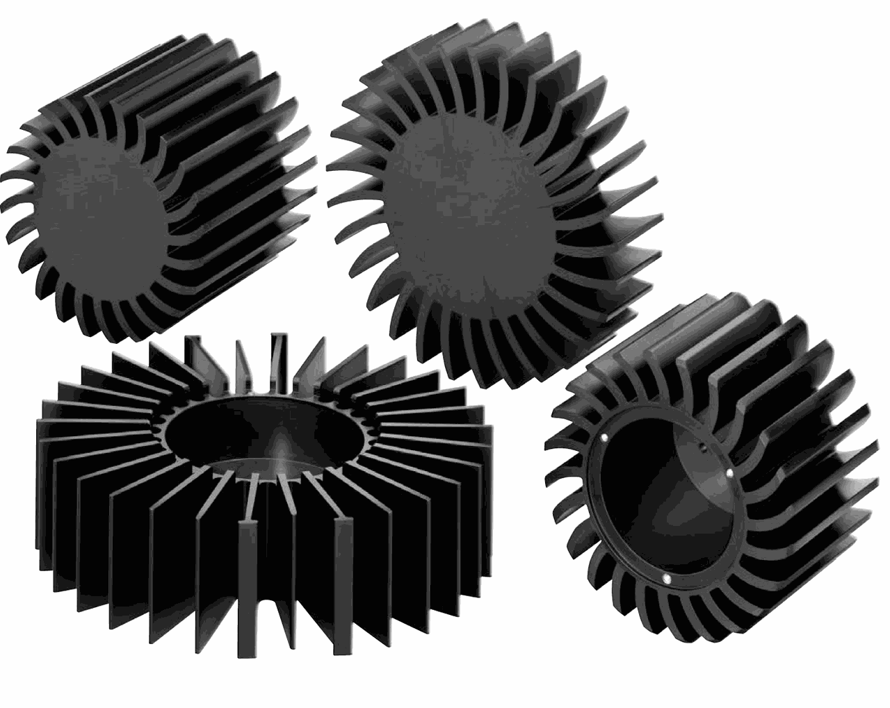
The physical processes in the semiconductor layer create power losses which are converted into heat losses. A live semiconductor creates “heat loss” due to electrical resistance which occurs as a result of the collisions of the electrons and atoms when switching binary modes. Frequency-related charge shifting increases the energy requirement and thereby causes this “heat loss”. The more often a switching is performed, the more heat is created. Generally the following rule applies: for each temperature increase of 10°C the expected life-span of electronic components and systems is reduced by approx. 50%. This fact clearly shows that efficient heat management is unavoidable. The easiest way of limiting the temperature is in accordance with the principle of increasing the surface of the component to be cooled by using suitable media, such as a good conducting heatsink (Figure 1). In accordance with its definition, a heatsink is a mechanical part which is conductively connected to a heat-producing, electronic component, with the aim of discharging heat from the component to the surroundings. Figure 1: Specially adjusted aluminum heatsinks to the respective application for a long LED life
To understand the connections of the cooling, an explanation is needed of the physical key terms of heat quantity, thermal output and heat flow as well as the temperature. Kinetic heat theory defines heat as a molecular movement, i.e. a solid becomes warmer the stronger the molecular movement is. The heat quantity is thereby the total energy of all moving molecules in a medium. Physically, the heat quantity is an energy form and is stated in Joules [J]. The work ΔQ performed over a period of time Δt is stated as a quotient (ΔQ / Δt = P) and the thermal output (P) in Watts [W]. As this thermal output is undesired when running electronic systems and components due to the conversion of electrical energy into heat, this is also called a power loss. The heat quantity per time unit flowing through electric components when in operation is called the heat flow [W]. The kinetic energy content of the molecules of a solid is called the temperature, whereby the unit [°C] and Kelvin [K] are compared.
The actual heat transfer is performed by conduction, convection and radiation. The conductive transfer of heat (thermal conduction) is a molecular heat propagation in media such as solids or static fluids. The radiative heat transfer (radiation) is a transfer of electromagnetic waves between two surfaces, while the convective heat transfer (convection) occurs between solid surfaces and the circulating fluid (air). Here material parts of a medium change their position in the room, if, for example, an uplift is created by a temperature-altering change to the density of the air (free convection). All three transfer methods are present, to various extents, in a heatsink.
Production of Heatsinks
Selecting a heatsink by considering the mechanical conditions and requirements as well as thermal criteria is extremely important for the long-term and safe functioning of modules, devices or systems. Making the correct choice of heatsink based merely on the dimensions, length, width and height is no longer enough. To assess the quality it is just as important to gain an understanding about the production-related conditions which have to be observed right from the start of the projection phase because they have considerable influence on the overall quality. The materials used for the heatsink mainly consist of aluminum alloys which have a good relationship between price, performance, volume and weight, and are also relatively easy to mechanically process. The specific heat conductivity (λ) of a material is to be strictly determined for good heat conductivity. The alloys used have values of λ >200 [W/m∙K] and are common in diverse sub-divisions.
In particular, the mechanical criteria and tolerances for the extruded profiles used have to be taken into account in the overall concept, as the manufacturing process and the achieved tolerance levels achieved are subject to international standards. Here the heatsink is often a component installed in a device which is always to be viewed in connection with other components. Produced in an extrusion process, heatsinks consist of so-called wrought alloys, i.e. when forming the heated aluminum material (to approx. 480°C) it is pressed by a die-plate, with the inserted heatsink geometry negative. The alloys used, mainly contain aluminum, magnesium and silicon and are called EN AW alloys in Europe. The abbreviation EN stands for European Norm and AW for Aluminum Wrought. In the industrial heatsink sector the alloys EN AW 6060 (previously AIMgSi0.5) and 6063 (previously AIMgSi0.7) are mainly used as the standard materials for extrusion profiles which cover the biggest share of corrugated heatsinks. The strength category is T66 (previously F22) in accordance with DIN 755-2 with a tensile strength (Rm) for the alloy EN AW 6060 of approx. 195-215 MPa and for EN AW 6063 approx. 225-245 MPa. Special alloys and other strength values can, of course, be produced but they require precise testing and are severely dependent on the tonnage.
The high deformation forces generated during the extrusion process induce corresponding high tolerances on the profile, which is why great efforts have to be taken to minimize these tolerances. The underlying DIN standards allow a plus/ minus tolerance range, depending on the size of the profile, ranging from a few tenths to several millimeters. Here not just the length, width and height of the profile have to be taken into account, but also the angular deviation (incline), twisting and plane parallelism as well as the wall thickness tolerance or curve (convex/concave) of the cross-section. For heatsink profiles with a circumscribed circle of less than/equal to 350mm (precision profiles) the press tolerance as per DIN EN 12020 applies, while DIN EN 755 applies to profiles with a circumscribed circle of greater than 350 mm. The production of profiles with a limited tolerance field is possible after careful consultation with the heatsink manufacturer, depending on the profile cross-section, although due to the low flow rate per time unit when extruding there are often additional costs. The total of all the advantages of wrought aluminum profiles, such as the relative low unit and profile tool costs, the easy creation of prototypes, the good thermal conductivity of the base material, the relatively low weight, the good thermal resistance and the wide range of versions available on the market make heatsinks an efficient and attractive cooling concept.
Thermal Resistance and Heatsink Calculation
The thermal technical data of the heatsinks is determined by the manufacturer using calculations, simulations or even laboratory tests. Even once the users are aware of the technical background of cooling, the selection of a suitable heatsink for specific problems is still not particularly easy. Accompanying boundary conditions need to be observed as they often have such an effect that they should not be disregarded. Often the optimum circuit-technical positioning of the electronic components cannot be harmonized with the best heat-technical solution.
The selection and use of heatsinks requires an assessment of certain criteria, which have a considerable effect on the selection of a suitable heatsink. Essentially the selection should be made after listing the thermal criteria (datasheet from the manufacturer), the calculation of the thermal resistance and considering the installation situation and the space available. In particular the calculation of the thermal resistance provides a very helpful statement about the required heatsink size, geometry and length. According to the physical definition, thermal resistance is resistance against the flow of heat in solid, liquid and gaseous media. This is inversely proportional to the heat resistance, i.e. the lower this value the better the component or heatsink dissipates heat. The unit for thermal resistance (Rth) is stated in Kelvins per Watt [K/W]. This is calculated according to the 2nd main clause of thermodynamics from a temperature difference which the power loss to be cooled is divided against. The known dependencies from thermal technology and the assessment of thermal management therefore cause temperature and power loss dependencies with the calculation of the general thermal resistance using the formula:
Rth = d / λ ∙ A
whereby the influencing factors consist of
d thickness/length of the heat path in [m],
λ the thermal resistance of the material in [W/mK] and the
A cross-section surface of the heat transfer in [m.].
When using the given material values and known temperature or power losses details can be found in the manufacturer’s datasheet, and now the thermal resistance relevant for the choice of heatsink is calculated in accordance with the Ohm’s law. The temperature difference ΔT between the semiconductor junction and the surroundings (ΔT = TJ – TU) of the heat sink is calculated from the power loss PV in [W] and the total of all thermal resistance Rth. The total thermal resistance consists of a series connection of the individual partial resistances along the thermal pathway, which has to overcome the thermal current. This leads to the following general rule:
Rth = ΔT / PV - (RthG + RthM) =
TJ - TU / PV - (RthG + RthM)
For an estimated calculation the additional thermal transfer resistance (RthG = inner thermal resistance of the semiconductor and RthM = thermal resistance of the installation area/ thermal conductor material) can be added to the calculation, even with a charged temperature reserve of the maximum junction temperature of the semiconductor. With the thermal resistance calculated in this manner, a heatsink can be selected under consideration of the further boundary conditions and using the numerical details, diagrams or graphics (Figure 2) shown in the catalogues of the heatsink manufacturer. The right thermal resistance for the stated cross-section is calculated at the intersection of the characteristic curve with the associated heatsink length.
 Figure 2: The thermal resistance Rth compared to the required heatsink length with the stated cross-section area of the heatsink
Heatsinks for Natural Convection
In the development of the electronic design, a calculation of the required space, weight, volume and installation space for the heatsink should be carried out right at the beginning, as the calculation of the thermal concerns directly entails the ascertainment of the cooling system and therefore the installation size. If the special features of the thermal path are not considered when creating the design, subsequent changes to the specifications are often annoying, time-consuming and cost-intensive.
The geometric dimensions of the corrugated heatsink (Figure 3) should be determined with free convection on the respective component size of the semiconductor, including the LED, so that the heatsink contact surface, normally on the base, is used homogenously and the heat input can occur across the whole surface. For isolated and very small heat input surfaces, as well as for time-dependant (transient) heat input, the heatsink design under free convection has to be especially observed. In these thermal conditions it is necessary, for the effective cooling of the electronic component, to quickly absorb the emitted heat from the component through the heatsink, in order to prevent the junction temperature being exceeded. This may be linked to the use of contact surfaces for the distribution of heat which are form-fitted to the heatsink, e.g. made of copper (λ= 380 W/m∙K), or made using high-performance heat-conductive anisotropic graphite film. Depending on the application and the installation conditions of the semiconductor to be cooled, in the heatsink selection process you should always pay attention to the correct ratio between the heatsink width and length, base thickness, fin height, thickness, quantity and distance, while also taking into account the calculated thermal resistance and the component size.
 Figure 3: The size of the heatsink has to be adjusted before each design-in to the size of the electronic component to be cooled
The length of the heatsink also has to be adjusted to the dimensions of the component. As evident in the picture (Figure 2), the heatsink goes into a kind of saturation range (linear curve) above a certain length, i.e. at a certain length is does not make any sense from a heat technical perspective to increase the length of the heatsink. An improvement of the thermal resistance now occurs by increasing the surface due to adjusting the width of the heatsink or the height of the fins. Particular attention also has to be paid to the correct fin distance of heatsinks that are ready to use. The surface cannot be increased as desired by the number of cooling fins, as with the structure of the heatsink you have to be aware that depending on the different geometry and temperature fields the individual fins can influence each other, e.g. as a result of a fin distance that is too low. Cooling under free (passive) convection occurs due to a difference in the density of the surrounding air caused by the temperature differences, in the form of a convective exchange of heat. The heated air is specifically lighter, there is uplift where cooler air flows and continual air movement is thereby established. In the convective transfer of heat the different types of fin geometries and the distances of the fins from each other are subject to the so-called barrier assessment (bypass effect). This barrier is the accumulation of non-moving air molecules on the fin walls and prevents a direct transfer of heat to the flowing medium (air). If the boundaries of two adjacent fins of a heatsink grow together, the transfer of heat is very strongly reduced. A greater fin distance is needed; high fins in particular need a greater distance as the boundaries above will be thicker.
The height of the fins of a heatsink, in a vertical position, to the base plate, should not be exaggeratedly high for economic reasons. This does not just depend on the material, but also on the cooling method currently applied (passive or active convection). The optimum fin height or fin effectiveness can be relatively easily calculated using analytic methods e.g. Wutz. Essentially it has to be determined that for higher fins the effectiveness does not increase significantly, as not much more heat can be transported to the tips and the fin tips virtually “cool down”. The greater the fin height used, the thicker the individual heatsink fins. The preferred installation position for heatsinks in natural convection is determined according to the principle of the stacking effect (vertical floor area), in which the heated air can rise by convection current (uplift) without obstacle (Figure 4, left). Some deviating installation positions lead to significant efficiency losses (Figure 4, right) which have to be taken into consideration in the thermal calculation.
 position of heatsinks for free convection should always be taken into account (right image shows an inappropriate mounting solution)") Figure 4: The correct installation (left) position of heatsinks for free convection should always be taken into account (right image shows an inappropriate mounting solution)
Figure 4: The correct installation (left) position of heatsinks for free convection should always be taken into account (right image shows an inappropriate mounting solution)
Machined Heatsinks and Surface Treatment
The connection of the component to be cooled to the heatsink is particularly important, as if the heat transfer from the component to the radiator is bad, the thermal convection and heat transfer are reduced and the component temperature is considerably increased. This can limit the function and an uncontrolled increase in temperature or even destruction is possible. The optimum heat transfer between the component and the heatsink is only reached if the tolerances, irregularities and roughness of the surfaces to be connected, which are unavoidable due to the production process, are equalized and air pockets which prevent the transportation of heat are avoided.
In the event of the machined processing of a heatsink, such as the milling of corners, drilling of holes or threads, the general tolerances as per DIN ISO 2768, with the tolerance class (m) for medium, normally apply, provided nothing else is stated in the diagram. If face milling is performed on the base surface or mounting area for electronic components due to irregularities, it has to be ensured that the stated thread depths can be reduced, as the base plate of the heatsink is equally thinned due to material wear. If the cutting diameter is smaller than the area to be cut in the face milling for production reasons, so-called milling edges are visible due to parallel milling. They are edges that measure a thousandth or at the most, a hundredth of a millimeter and could have an influence on the functioning of the heat transfer or the assembly. If these cutting paths are not to be visible, it is advisable to state in the diagram the areas where no milling edges are desired. The explanations given show that allocation and classification of pressing and production tolerances are thoroughly unproblematic, if the available options for influencing them are used knowledgeably. A detailed summary of the criteria for selecting a heatsink, related to the respective area of application, also allows costs and delivery times to be reduced.
Surface requirements for corrosion protection or even on the decorative appearance have a considerable influence on the effectiveness of the heat dissipation of a heatsink. For aluminum heatsinks anodized surfaces are very sensible, regardless of their color. Alongside the known corrosion protection effect of anodized surfaces, when these oxide layers (12-15 μm) are applied there is a surface structuring in the nanometer range. As a result, the heatsink gets improved heat dissipation of approx. 8% to 10% in free convection. The physical connection between heat dissipation, thermal radiation and the emission factor is shown by the formula:
Q = ε σ A T 4
with
Q radiation power,
ε emission ratio 0.55 (for black anodized aluminum),
σ Boltzmann constant,
A surface of the radiating solid,
T temperature of the radiating solid (in Kelvin).
As already stated in the afore-mentioned formula, anodized layers have an emission factor of approx. 0.55, whereby coated surfaces, e.g. for decorative applications, have an emission factor of > 0.9. A negative point of this is that anodized layers have a heat conduction value which is approximately 10 times lower than that of aluminum. To reduce the thermal transfer resistance it is therefore sensible, in heat-technical threshold ranges, to remove this anodized layer in the assembly area of the electronic components by milling, after the anodizing process.
Conclusion
One of the most urgent problems in electronics today, including LED technology, is the efficient cooling of electronic semiconductor parts. Due to the high processing speeds, constant minimization of components with increasing power losses, the thermal problems have a significant effect on a possible system malfunction or in the worst case even the destruction of a component. Advanced heatsink technology is therefore a must for efficient thermal management. For some applications, tailor-made solutions (Figure 5) are the first choice. Established and experienced manufacturer of heatsinks like Fischer Elektronik, with its 40 years of experience, provide such tailor-made solutions and production feasibility.
 Figure 5: Customer-specific processed heatsink solutions with efficient thermal management adapted to the respective application
