Concepts to Overcome Lifetime Issues of LED Drivers
Lighting technology has changed significantly in recent years after a century of little to modest advancements. LED luminaires offer advancement in lower power consumption and expected life. Maggie Nadjmi, EE Product Manager at SL Power Electronics, explains why this new technology will probably not meet the life and reliability expectations if no attention is paid to the drivers and power supplies used to power LEDs. She discusses the main components affecting lifetime and how to eliminate them or design a product to still achieve the desired lifetime.
The life of an LED driver can be defined as the length of time it can operate and continue to meet its specifications. The limitation of useful life is often due to two types of components that are known and well-documented wear-out mechanisms. These components are aluminum electrolytic capacitors used for filtering/energy storage and the optocoupler for high-voltage isolation and electrical noise rejection between different voltage potentials. In this article, we will examine the essential requirements for a proper thermal design of an LED driver and selection of highly reliable electrolytic capacitors. We will also review high-performance optocouplers with photo-IC output that have employed the long life-emitting light technology.
Aluminum Electrolytic Capacitors
Aluminum electrolytic capacitors slowly lose their electrolytes due to deterioration of the rubber seal and diffusion of the electrolyte. The loss of electrolyte causes a decrease in capacitance and an increase in ESR (Equivalent Series Resistance). This results in a decrease of holdup time and an increase of output voltage ripple and noise. Sometimes it also results in malfunction or no-start conditions of the control circuits.
The electrolyte loss depends on the temperature of the capacitor. Every 10°C reduction increases the life by a factor of 2, according to the Arrhenius Law (Figure 1). The graph shown is for 10,000 hour, 105°C rated capacitors. Capacitors are available with rated life up to 12,000 hours at 105°C and 5,000 hours rated life at 125°C, which equals 20,000 hours at 105°C. However, capacitor manufacturers do put an upper limit of 15 years (130,000 hrs) on the capacitor’s life. Figure 1: Capacitor life vs. temperature
The temperature of the capacitor is the sum of the system’s ambient operating conditions and the temperature rise of the power supply itself. This raises the temperature near the capacitors and the capacitor’s internal heating due to ripple current. The system’s ambient operating conditions are determined by the particular application. The temperature rise of the power supply can be derived from the power supply’s efficiency curve and the surface area of the power supply. The capacitor’s rated ripple current is already factored into the capacitor’s life specification. For that reason, as long as the capacitor is operated at the same or lower than the rated ripple current, it can be ignored.
 Figure 2: Power supply TRise vs. load, input voltage, ambient
Design Measures to Improve E-Cap Lifetime
Design measures can mitigate the effects of temperature by prudent thermal management. One important measure is the location of the capacitor to reduce the impact of heat from surrounding components by radiation. Another important design consideration is providing a suitable path for thermal conduction, including applying appropriate thermal interface material of high thermal conductivity and heat sink at appropriate locations. It is also important to avoid placing heat components on the reverse side of the circuit board (under the capacitor).
The temperature rise of a typical 130 W power supply that measures 5x3x1.5 inches with convection cooling is shown in Figure 2. Offering some form of conduction cooling to a base plate or a fan to provide airflow can reduce the temperature rise of the power supply.
The life of a fan is often stated in terms of the L10 life expectancy. L10 specifically refers to the amount of time it takes for 10% of a group of fans to fail. The L10 life is often in the 60-80,000-hour range and is almost entirely based on the bearing system, the lubrication used, and on the ambient temperature. However, the temperature effect is less pronounced than that of aluminum electrolytic capacitors [1].

Figure I: Use solid heat-sinks to add more contact area with cold plate
Figure II: How to attach cold plate to maximize heat transfer
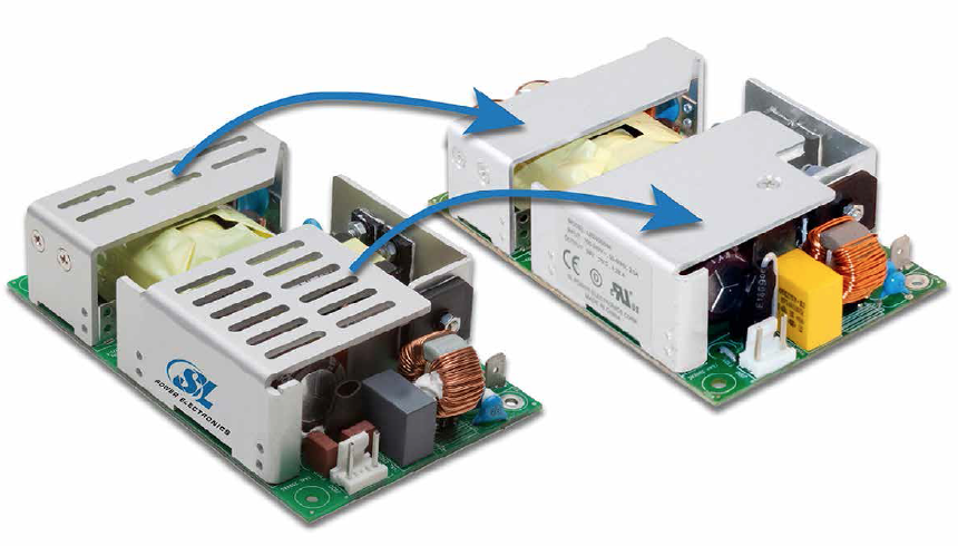
When the power supply uses 10,000 hour life-rated 105°C capacitors, the capacitor life exceeds the life of any available fan. This eliminates the need for a fan. SL Power’s LB240 power supply family with 130 watts of conduction power at 70C is an example of such a power supply with e-caps rated at a minimum of 10,000 hours at 105°C. The power supply is packaged in industry standard 3x5 size and has an on-board filter to meet the EN55015 EMI class B.
If fan or convection cooling is not possible and the lighting fixture has a metal chassis, the better alternative is conduction. In order to convert a convection-cooled power supply to a conduction-cooled one, the required minimum to provide a functional and safe alternative is to transfer the heat from the power supply to a metal chassis. These steps are highly recommended and if not followed, the outcome will result in a short life of components, especially for electrolytic capacitors.
Optocouplers
Optocouplers are commonly employed in a number of different applications, including power supplies and LED drivers. However, there are still concerns regarding the optocoupler operating lifetime since LED light output power decreases over time. To understand the steps that are taken to mitigate this concern, it is important to examine the process that one industry leader in optocouplers uses to predict the LED reliability stress data under accelerated conditions.
To project expected LED lifetime performance, the Black Model, (a generally accepted empirical model developed at the end of the 1960s by J.R. Black) is used to estimate the mean-time-to-failure (MTTF) of wire associated with electro-migration. This analysis provides designers with greater confidence and design flexibility so they can specify the most appropriate LED forward input current for their applications. An Acceleration Factor (AF) based on the Black Model can be used to correlate the actual HTOL stress test data points. These are taken at elevated temperatures and stress levels in short periods of time to the expected lifetime, according to the actual application and operating conditions of the optocoupler.
To understand the elements of optocouplers, let’s review the structure of such a component. It uses an LED to transmit digital or analog information across an isolation (or insulation) barrier (often just an air gap). On the other side of the barrier is a light-sensing detector that converts the optical signal back into an electrical signal. Designers can set an input current-limiting resistor that defines a recommended input drive current (IF) to the LED to produce the desired light output. However, the optocoupler’s LED quantum efficiency (total photons per electron of input current) decreases over time due to thermal and electrical stressing of the LED PN junction. A stress testing is performed to determine LED reliability for periods of continuous operation up to 10,000 hours for the various LED types used in different models of their optocouplers.
One of the stress tests, a High Temperature Operating Life (HTOL) test, is performed with the LED operating at 125°C and a continuous IF of 20 mA. The Current Transfer Ratio (CTR) is an electrical parameter usually specified for an optocoupler. CTR is defined as the ratio of the output collector current (IC) caused by the light detected by the photodiode to the forward LED input current (IF) that generates the light, and is denoted as a percentage. Designers can use the change in CTR over time to gauge the degree of LED reliability.
Current Transfer Ratio:
CTR = (IC/IF) x 100%
The input current and temperature cause heat stress in the LED crystalline structure. Thus, even though IF stays constant, the light output from the LED decreases over time. The photodiode’s IC and CTR will thus decrease. At each pre-determined point of stress test hours (168, 500, 1000 hours, etc.), IC is measured, and the CTR is calculated. Then, LED lifetime performance is plotted using this collection of data points to show the change in CTR versus the number of hours that the stress test runs.
LED Types in Optocouplers
The LEDs in optocouplers are fabricated from either Aluminum Gallium Arsenide (AlGaAs) type 1 and type 2, or Gallium Arsenide Phosphide (GaAsP). Type 1 AlGaAs LEDs are mainly used in optocoupler product families of wide-body 400 mil DIP-8 and 500 mil DIP-10 packages that house digital optocouplers, isolation amplifiers, gate drivers and IPM drivers. Type 2 AlGaAs LEDs are mainly used in optocoupler families that handle high-speed digital signals and low-power 10 Mbit/s digital optocouplers. Lastly, the GaAsP LEDs are used in a broad range of optocouplers, from digital optocouplers, analog optocouplers, gate drivers for intelligent power management and many other applications.
Each LED type employs a different manufacturing process (diffusion type or epitaxial growth), and different doping content concentration. This allows the LED designer to customize the LED light output power versus current flow to address the different speed and power performance requirements of the optocoupler. Among the three different LED types, GaAsP-based LEDs are the most mature, but have the lowest light output power, while AlGaAs type 1 offers the highest light output power. This allows AlGaAs type 1 LEDs to be used in the more stringent isolation applications that require high creepage/clearance distances inside the optocoupler package. An AlGaAs type 2 LED has a performance level that falls between the other two LED types and can be used in a wide range of applications that require speed or power performance. All three LED types have similar characteristics, with < 10% loss from the original CTR value after 30 field years of typical operation conditions.
In general, there are three basic factors to consider to maximize the optocoupler LED operating lifetime:
- Operate the LED at a lower IF
- Operate at lower duty cycle (less than 100%)
- Operate at a temperature of less than 125°C
Conclusions
Electrolytic capacitors and high-performance optocouplers are critical components in LED driver design and because of this, their reliability can have an outsized impact on the overall product lifetime. By managing the complete thermal characteristics of the design, optimizing the selected cooling mode (convection or conduction) of the power supply based on end use requirements, and reviewing stress test data to select optocouplers compatible with given parameters to assure the highest MTTF, designers can maximize LED reliability and the long life for their products.
References:
[1] http://www.nmbtc.com/fans/white-papers/fans_ball_vs_sleeve.html
