Cost Saving Potential with Automation and Well Designed Processes by BJB GmbH
The manufacturing of modern LED luminaires and conventional fixtures has some similarities as well as some distinct differences that result in added challenges. Automation, in combination with a well-conceived product design and process combined with well-matched components, allows for economical manufacturing without compromising production quality and, consequently, reliable, high performance, and high quality luminaires. Olaf Baumeister, Head of Product Development and BJB-Automation at BJB GmbH, explains and discusses technical challenges, successful concepts and solutions.
LED is the technology of the future. This was impressively demonstrated at the world’s leading trade fair for architecture and technology, Light+Building, in Frankfurt-am-Main in March 2014. LED luminaires for both indoor and outdoor applications dominated the range of products on display. The increased demand for LED solutions, however, also necessitates action from manufacturers because the prices which can be achieved on the market are falling. This can be offset to some extent by the LED chips, which are following the general decline in prices in the semiconductor industry - while simultaneously offering improved lighting parameters. In addition, the trend towards more LED luminaires is resulting in a demand for larger quantities, which, in turn, means a change in production requirements. The industry is currently between small-scale craftsmanship and industrial mass production.
This represents a challenge for the manufacturer, but is also an opportunity to put low-cost solutions on the market and gain market share. The question then arises of how the production of LED luminaires can be simplified, processes streamlined, and a consistent quality achieved while complying with the safety measures required when working with semiconductors. The competitiveness of the luminaire manufacturer ultimately depends on these factors.
A Consistent Approach to the Growth Market for LED Luminaires
In many ways, the requirements for the production of LED luminaires resemble those for the production of luminaires with conventional light sources: Automated production lines with wiring robots, such as the ADS systems, have long been in effective use. ADS stands for “Automatic Direct Wiring of Standard Components”. Various components of the “modular machine system” can be combined to meet individual needs, i.e. can be adjusted to the exact requirements of the luminaire manufacturer. For small or medium batch sizes, there are individual stand-alone units and modular systems consisting of a loading and unloading station, wiring station and test station. At the other end of the spectrum, there are complete production lines with automatic assembly for very large quantities.
ADS product lines [1] for conventional technology have been adjusted to meet the requirements of LED processing and separate test stations have been added. For this type of processing, the individual stages are generally automated and the luminaires themselves optimized for automatic wiring, resulting in the manufacture of high-quality, low-cost products.
Even though the trend towards miniaturized luminaires in the last few years has meant that robot movements have had to become considerably more delicate, the wiring of LED luminaires represents a new dimension. It is also necessary to adapt the processes to the special requirements of the LED light source – i.e. a semiconductor component.
Due to the Semiconductor
When processing LED components with ADS systems, an important consideration is the avoidance of electrostatic discharge (ESD), a phenomenon which has previously played a relatively low priority role in luminaire production. Electrostatic discharge (ESD) can damage LEDs or cause them to fail completely.
ESD is a spark or disruptive discharge resulting from a large potential difference in electrically insulating material that causes a very short, high-voltage electrical impulse. The potential difference usually results from a build-up of static electricity due to friction. Many everyday activities generate very high voltages. In the case of static discharge, a human being only notices electrical voltage from a level of about 3,000 volts. Semiconductor components can be damaged by as little as 100 V. The strength of the voltage impulse generated is very dependent on relative humidity as well as the intensity of the contact, the materials involved and the speed of separation [2].
ESD can damage LEDs so severely that they fail completely. As no more light is emitted, the LED remains dark during the optical inspection. In addition, it is no longer electrically conductive, so that other intact LEDs, which are connected in series, fail to light up. This type of failure is immediately recognizable. However, ESD damage can also have the effect that LEDs still emit light at first, but quickly become darker.
Such damage can be prevented by ESD-protective measures for machines and objects, as well as for the different stages of work. Earthing is an important measure. A fundamental rethink is also necessary for staff that has previously been involved with more robust lighting technology. For example, the wearing of ESD-protective clothing is essential. This includes a special wrist strap, conductive footwear and heel straps on both feet to ensure constant contact to the earthed floor.
Neutralization is also effective. An ionizer is used for this purpose. This generates billions of charged particles, which neutralize the static charge in an insulator.
Wiring systems also have to be designed to ensure that no electrostatic discharge can occur. ESD protection has top priority here and has to be implemented with particular reference to the standard DIN EN 61340-5 parts 1 and 3 [3, 4]. For this reason, the panes of the ADS protective enclosure are of statically dissipative polycarbonate. Special connecting elements provide an electrically conductive link between the aluminum profiles. In addition, the protective hoses that supply the wiring tool are made of conductive plastic (Figure 1). The wire that is to be processed is also earthed.
There is therefore a whole package of ESD measures to ensure that LED luminaires that leave the automated production facility are fully functional. Figure 1: The wiring robot and wiring tool are complemented by stations for test and assembly work. All components are specially designed for wiring LED luminaires with their special requirements, in particular with regard to avoidance of ESD
Handling Optimized for Speed
Standard wiring systems and test stations, which are of modular design and therefore custom-configurable, fulfill these requirements. Special tailor-made machines provide well-designed, task-specific solutions for automatic assembly, wiring and testing.
All process stages are designed to provide optimum flexibility and speed and run automatically [5]. The work piece carrier travels back and forth to minimize travel times for the operating personnel. So, while one person is manually removing the luminaire from the previous cycle, the other person is putting in place a prepared luminaire, i.e. the pre-assembled luminaire housing with LED modules, control gear and terminal blocks, for the following wiring cycle. There then follows the automatic wiring process with a 6-axis robot and a specially developed multifunctional wiring tool with cable feed (Figure 2).
 Figure 2: The wiring tool with cable feed enables precise wiring of LED luminaires even when space is extremely limited
The wire is transported to the wiring tool from a wire barrel that holds up to 12 km of wire. The wiring tool cuts the necessary wires to length fully automatically (i.e. during the wiring process), strips the ends, and inserts them into the appropriate contacts in the luminaire. The pattern of wiring and the movement and configuration of the robot can be specified precisely. The sophisticated design of the wiring tool means that even inaccessible locations in miniaturized LED luminaire housings can be reached without difficulty.
Stations for test and assembly work complete the range. These machines boast an intuitive user interface. Separate offline software, which can be installed on a stand-alone computer, enables new wiring programs to be drawn up, or existing programs to be modified independently of the machine.
Comprehensive Test Procedures
In complex wiring systems, the LED luminaire that has been wired is automatically transported to the test station by the work piece carrier. There, detailed tests are carried out, some of which are prescribed for conventional luminaires in accordance with DIN EN 60598-1 [6] to ensure product safety, while others, e.g. according to DIN EN 62031 [7], apply specifically to LED light sources.
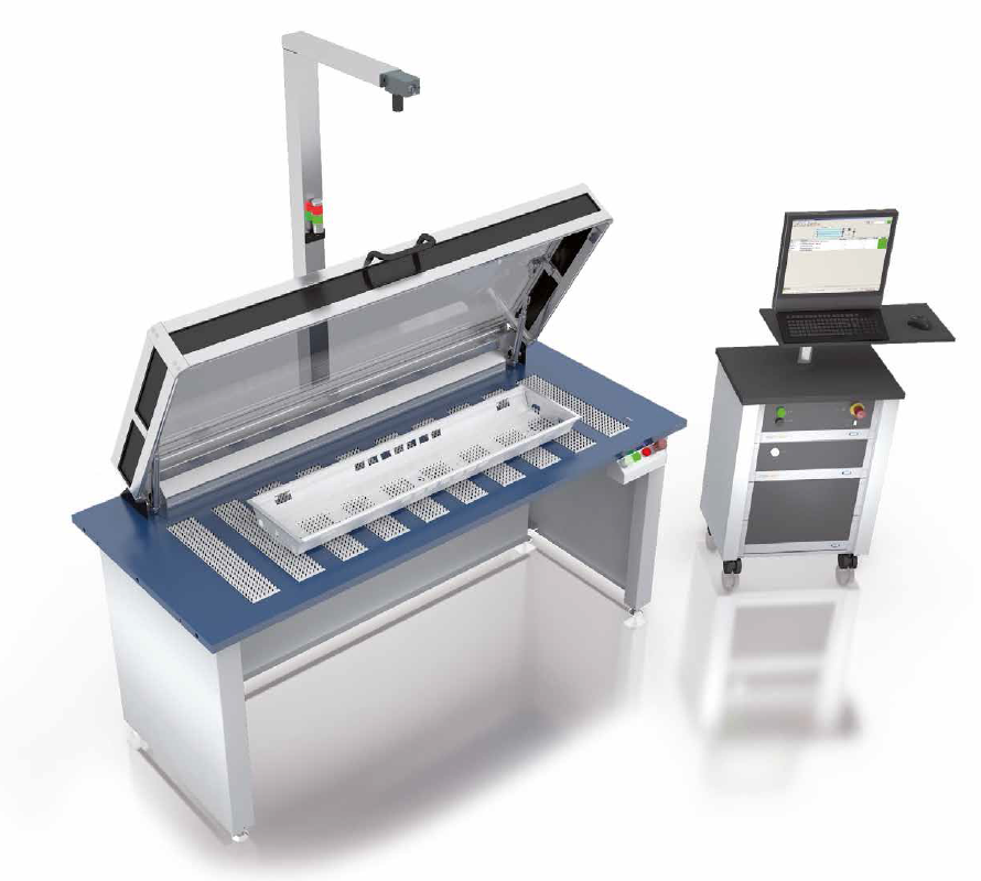
A suitable test bench is ESD-protected and has an earth bonding point for the operating staff. To enable the entire test procedure to be carried out (semi) automatically and unsupervised, or, alternatively, to provide visual protection, the bench is ideally also equipped with a safety hood that lowers automatically (in this case made of tinted polycarbonate). (Figure 3)
 Figure 3: The ESD-protected test bench with its safety hood of tinted polycarbonate, which lowers automatically, provides visual protection or, alternatively, the possibility of allowing the entire test procedure to be carried out unsupervised
Other equipment available for the test station is a compact tester or a more convenient PC-based version in combination with a camera system, which examines the individual LEDs in a luminaire. This provides an objective result showing whether all LEDs are actually lighting up. An LED that remains dark may indicate ESD damage, a defective soldering point or a circuit interruption. The camera-based procedure has clear advantages over a visual inspection by the operating personnel, for example by eliminating errors due to fatigue.
Protective conductor tests, insulation resistance tests and functional tests can be carried out with the basic version. The more intelligent version offers additional tests via the DALI/DSI interface and 1-10 V interface for control gear for luminaires with a dimming function. The result of the final test of the luminaire is displayed on the monitor and recorded for subsequent evaluation. The test result can also be stored in an Access or SQL database.
For Specified Operation
The DALI/DSI interface can also be used to combine the calibration of the control gear with the final test of the luminaire in one work stage using the intelligent system. This ensures that the LED modules are subjected to the “right” constant current - because there are now universal converters that are not designed for standard values like 350 mA, 700 mA or 1050 mA, but cover a wide constant current range.
In addition to this direct “digital” calibration during testing, there is the possibility of a mechanical-electrical calibration with a resistor. For this purpose there is a specially developed “Set’n’Drive resistor”, which can be inserted on the secondary side of the LED converter once wiring has been completed. This can be done either manually or automatically using the wiring tool of the ADS wiring system. The three gripping positions on the housing enable insertion to be carried out at any angle. For automatic processing, the Set’n’Drive resistors are correctly pre-positioned in trays in the area of the work piece carrier. This also ensures an error-free calibration of the control gear.
Components for New Requirements
Cost saving in automated LED luminaire production can be improved even further by the use of standard components. To maintain a position as a capable partner to the lighting industry in the changeover from conventional lighting to digital lighting and cope with the resulting challenges, it is necessary to have an interdepartmental innovation team with representatives from Research and Development, Product Management, Automation, Engineering, Quality Assurance, Sales and Marketing. Their role is to develop ideas based on their many years of experience, in particular regarding the extensive global sales network and their direct access to users in the luminaire production sector. Tailor-made ADS systems are based on the analysis of the tasks to be performed as well as the luminaire to be manufactured and how its layout can be improved to make it more suitable for automation purposes.
Only a systematic approach, as far as possible from the customer’s perspective, leads to LED-specific solutions. Expertise in “conventional” connection technology combined with knowledge in the field of automated luminaire wiring produce well-designed components and systems. The objectives are simplification and economic rationalization while maintaining a constant high quality. A prerequisite is that components have to be adapted to the specific characteristics of the LED light source – such as extremely slim design - and fulfill the requirement for consistent thermal management. Such components then provide new freedom in luminaire design, resulting in significant added value for the luminaire manufacturer.
Components that save time and money through easier handling, for example through plug-in connection instead of soldering, have an equally beneficial effect. Without soldering, the components are not exposed to thermal stress during assembly. This, in turn, minimizes the risk of failure. Plug-in connection is also environmentally friendly as no soldering fumes are released and there is no exposure to pollutants. Ultimately, energy consumption is also minimized.
Delicately Designed Terminal Blocks with Variants
Terminal blocks and connectors precisely geared to the requirements of the LED age have the potential to improve and accelerate the automated production of delicate LED luminaires. SMD terminal blocks for rear-side wiring are an example. These are particularly advantageous in the case of luminaires with control gear on the rear side of the mounting plate (Figure 4). Unlike conventional terminal blocks, these do not require the luminaires to be turned during assembly. The omission of this time-consuming process speeds up production time considerably. Because conductors, terminal blocks and control gear are now hidden “elegantly” behind the LED module, this intelligent type of wiring has the added advantage that individual LEDs are no longer obscured by untidily laid cables which impair their light emission. Due to the slim design, reflectors, optical and lens systems can be attached directly above the module.
 Figure 4: The SMD terminal block for rear-side wiring speeds up production of luminaires with control gear on the rear side of the mounting plate, as it is not necessary to turn the luminaire during assembly
With their slim design and plug-in technology, Board-to-Board connectors (B2B) represent an equally easy and efficient solution. They enable LED modules to be combined both mechanically and electrically to form endless light band fittings. No additional wiring is required, thereby reducing disturbing shadow formation. This concept requires no screws or tools, which also simplifies the installation process.
Use of these versatile connectors results in the LED luminaire having a “tidy” layout that is consistent with the characteristics and requirements of the light source itself and the prerequisites for low-cost automated production (Figure 5).
 Figure 5: The extremely compact connectors which have been specially developed to meet the requirements of delicately designed LED luminaires, such as SMD terminal blocks for rear-side wiring, Board-to- Board connectors or Push-to-Fix elements, minimize conductor requirements and ensure a “tidy” layout which is suitable for automation
Innovative Connection Technology with Multiple Benefits
The Push-to-Fix element (P2F), which can be used to fix LED modules and components, goes one step further. This represents a significant improvement over screw fixing and has established itself on the market in a very short time by providing considerable added value, not only in the assembly process, but also during luminaire operation. Consisting of a metal spring and elastic silicone (Figure 6), the P2F board fixing element exerts a constant pressure of 10 N and ensures excellent heat dissipation due to the large area of contact between the circuit board and the luminaire housing, with no bending. This is an important aspect, which has a significant influence on the life of LED luminaires [10].
 Figure 6: Consisting of a metal spring and elastic silicone, the Push-to-Fix element ensures a large area of contact between the circuit board and the luminaire housing, resulting in excellent heat dissipation
Due to its dimensional stability and temperature resistance, resulting from its virtually floating method of connection, the silicone ring can offset tolerances or compensate for thermally induced length variations in a component fixed in this way – in the case of a 560 mm long circuit board, this can be as much as 1 mm. The forces exerted during the automatic wiring of SMD terminal blocks can also be effectively absorbed by using the P2F fixing element.
The electrically insulating connection to the circuit board is shock and vibration resistant. There are five variants of the Push-to-Fix element, with different colored silicone rings, to cater for the usual package thicknesses of LED module and luminaire housing of between 1.5 mm and 3.6 mm. This fixing element is installed manually or by means of a special setting device, which is equipped with an automated feed system to accelerate the process even further (Figure 7). As well as the technical benefits it offers, the P2F concept has a considerable number of other advantages over the screw - it can perform several tasks at the same time and is quick and easy to install.
 Figure 7: The P2F fixing element can be installed manually or with a special setting device, which is equipped with an automated feed system in order to speed up the process even further
Conclusion
Basically, as experience in the conventional lighting sector has already shown, what is required to produce an optimum result is the combination of an LED luminaire layout suitable for automation, the appropriate connection components, and a tailor-made ADS system. In the “LED age”, what constitutes added value in an LED luminaire designed to be suitable for automation is the ability of a manufacturer to be faster, more efficient and less expensive, while at the same time providing superior quality. Automation delivers reproducible results.
References:
[1] ADS Master L Fertigungslinien. Automationslösungen für die Leuchtenindustrie. BJB, Arnsberg 2009
[2] Applikationsschrift: ESD Schutz für LED Systeme. Osram, München
[3] DIN EN 61340-5-1:2011-06Electrostatics - Part 5-1: Protection of electronic devices from electrostatic phenomena - General requirements (IEC 101/333/CD:2011). Beuth-Verlag, Berlin 2011
[4] DIN EN 61340-5-3:2013-11: Electrostatics - Part 5-3: Protection of electronic devices from electrostatic phenomena - Properties and requirements classification for packaging intended for electrostatic discharge sensitive devices (IEC 101/410/CD:2013). Beuth-Verlag, Berlin 2011
[5] ADSone 2.0 – Automatische Verdrahtung von Standardkomponenten und LED-Anschlüssen. Perspektiven erweitern, Technologien verbinden. BJB, Arnsberg 2013
[6] DIN EN 60598-1:2009-09: Luminaires - Part 1: General requirements and tests (IEC 60598-1:2008, modified); German version EN 60598-1:2008 + A11:2009. Beuth-Verlag, Berlin 2009
[7] DIN EN 62031:2013-09: LED modules for general lighting - Safety specifications (IEC 62031:2008 + A1:2012); German version EN 62031:2008 + A1:2013. Beuth-Verlag, Berlin 2013
[8] BJB///OEM-Line: Der Weg zur LED-Applikation. Fachinformation, BJB, Arnsberg 2014
[9] LED-Licht- und Verbindungstechnik. Zusatzinformationen für SMD-Leiterplattenklemmen 46.101 und 46.102. BJB, Arnsberg 2013
[10] Befestigungselemente für LED-Platinen, BJB, Arnsberg 2014
