DMI Specification Defines Electrical Interface between LED Drivers and Modules
Enabling LED modules and LED drivers to be fully interchangeable at the component level requires a specification for the electrical interface between the driver and module (DMI). Arnulf Rupp of Osram GmbH, a member of both the Zhaga Consortium and MD-SIG, explains the role of both organizations in developing and implementing a consistent, easy to use, cross-vendor DMI specification.
The rapid evolution of LED technology has catapulted solid-state lighting (SSL) from spearhead innovation into a phase of steady market growth within only a few years. The new phase of LED lighting brings its own challenges. While the benefits of LED-equipped lighting fixtures over products based on traditional light sources is now indisputable in most applications, LED technology itself is still in rapid development. Keeping designs up to date and competitive leads to frequent redesign cycles, which the lighting industry was not required to manage back in the days of halogen, fluorescent and high-pressure discharge lamps.
From design to delivery, even the availability of certain technology generations may be an issue from time to time. Updating designs, adapting LED drive currents for ever-improving LED lumen efficiencies, and redesigning LED layouts to accommodate the latest in technology, have all become time-consuming and expensive baseload activities in the development departments of the lighting industry. This calls for stable, easy to use and reliable design-in methodologies based on well-defined interfaces among the building blocks for LED lighting.
The Zhaga Consortium has done a very good job in providing terms and definitions to describe many of those interfaces in a vendor- and technology-neutral way. Until recently, however, Zhaga lacked definitions for the interface between the LED driver (also known as electronic control gear, or ECG) and the LED module.
From its outset, Zhaga purposely excluded the driver-to-module interface (DMI) from its scope, because standardization in that area was considered to be limiting to design freedom and technical progress. At that time, it was expected that LED drivers and LED modules would always be designed as a system, similar to driver-integrated light engines and LED retrofit lamps.
The industry, however, faced availability issues for all the desired combinations of features such as form factor, photometric properties, dimming interfaces and power grid voltages. A different solution had to be found. LED drivers and LED modules, if not integrated in one product, remain separate building blocks, and the system integrator must manage the matching of components along the DMI interface.
Demand for Standardizing the DMI
Driven by the need for a flexible matching of components, LED driver manufacturers invented adjustable or programmable constant-current drivers capable of covering a wide range of load conditions in one product. Such products are often called window drivers, current-adjustable drivers or programmable drivers. A multitude of techniques for setting the output current is available in the market; voltage-controlled output current, resistor setting, programming through the DALI line, programming through a dedicated setting interface, interfacing with additional circuits on the LED module, programming through modulated signals on the mains input, and near-field communication.
Even within the very common resistor-settable products, the actual resistor values for setting a given current may differ from one vendor to another. In addition, the terminology used by the manufacturers to specify output characteristics, operating ranges and setting methods have become vendor-specific in many details. As an example, the specified output voltage and current ranges may or may not include margins for setting tolerances or current ripple effects.
The confusion and inconsistency in the market leads to a strong need for harmonization and standardization. At the same time, the existence of all these technologies has largely eliminated the initial concern that standardizing the interface between the LED driver and LED module would limit design freedom and technical progress. A set of current-adjustable window drivers, which may even have overlapping output voltage and current ranges, is an ideal situation for designing new LED luminaires and for upgrading of existing products. What remains is the need for a consistent, easy to use and cross-vendor-standardized DMI interface specification. This is where a new industry alliance, the Module Driver interface Special Interest Group (MD-SIG), aims to serve the market.
MD-SIG and LEDset
MD-SIG is a global lighting-industry consortium introducing LEDset as a multi-vendor specification for the interface between LED drivers and LED modules. The alliance has a global focus and is open to all interested parties. It aims to simplify matching of components and to reduce the interchange risk resulting from deviating terminologies for the parameters defining the DMI.
When used in combination with specifications created by the Zhaga Consortium, LEDset will enable manufacturers of LED luminaires to interchange LED modules and LED drivers made by different vendors. For that purpose LEDset1, the first specification released by MD-SIG, provides a standardized method of current setting and will introduce well-defined parameter sets for both LED drivers and LED modules.
It is not the aim of LEDset1 to provide a one-size-fits-all solution. LEDset1 rather targets a wide range of simple constant-current LED boards connected with output-current-adjustable drivers. The system integrator still has to verify key parameters defined in the parameter set for component matching.
MD-SIG specifications are publicly available on the organization’s website (md-sig.org). The use of the LEDset logo on products, however, requires companies to be a member of MD-SIG.
The LEDset1 information interface is already available for download on the MD-SIG website. It defines how the output current is set during luminaire production or through information exchange between driver and module. The related power interface, defining the parameter set for the output characteristics of the driver and the operating range of the module, is currently a work in progress. Further specifications may follow, for example a digital interface for LED module to driver communication and programming.
LEDset Interface Characteristics
 Figure 1: Push-in resistor for configuring the drive current on the luminaire production line. The corresponding electrical setup is shown in figure 2
MD-SIG has chosen to start with a specification harmonizing the very common analog current-setting methods. Even such simple and lightweight technology can already fulfill many of the typical industry requirements for the DMI.
MD-SIG defined a set of minimum requirements the specification has to address. This minimum set also respects the needs communicated by Zhaga for independent interchangeability of drivers and modules. The minimum feature requirements are:
• Output current setting at the production line of the fixture OEM
• Plug and play option with the current setting circuit included on the LED module
• Cross-vendor parameter set for specifying window drivers
• Live current adjustment e.g. for an optional thermal de-rating
• Interfacing with multiple equivalent LED modules connected in parallel and/or in series
The LEDset1 interface uses a simple analog technique to realize the required features. A LEDset1 driver acts as a current-controlled current source. In un-dimmed operation, the driver output current equals the current Iset at the LEDset terminal multiplied with a fixed factor of one thousand. For the supply of the setting circuit, the LEDset terminal provides a fixed reference voltage of 5 V. The setting circuit is a current sink connected between the LEDset terminal and the lower voltage (LED-) output terminal. In the simplest case, the setting circuit can be a simple resistor with a value Rset of:

where Iout is the desired output current.
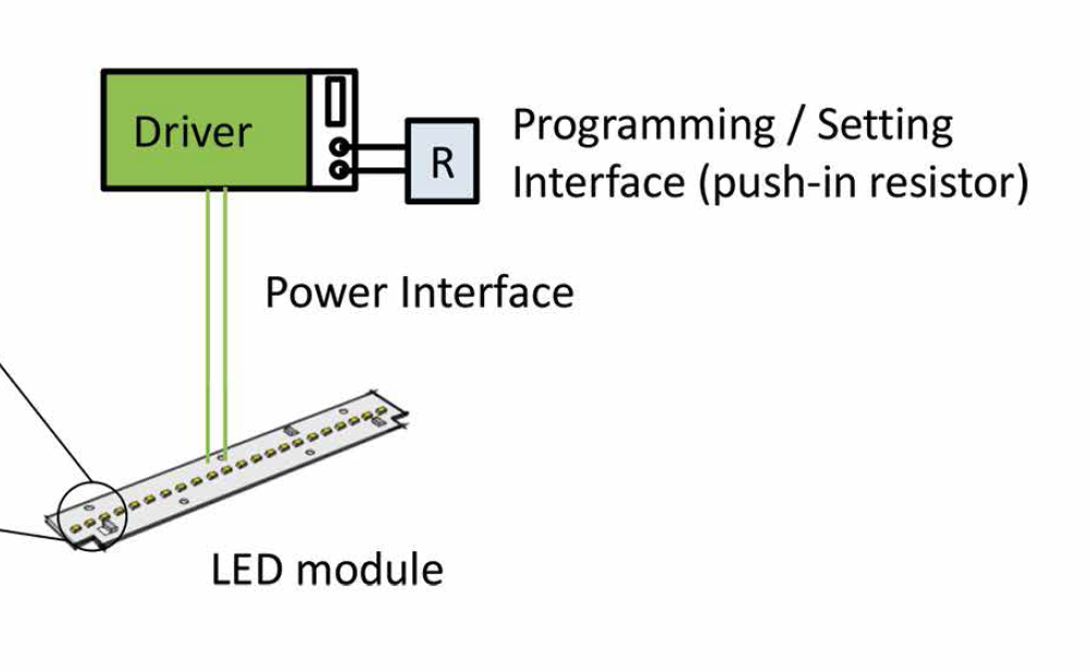
Figure 1 illustrates the case of a coding resistor plugged into the driver for setting the drive current. The schematic in figure 2 shows the electrical setup corresponding to the diagram infigure 1. The setting circuit may also be installed on the LED board; this would require a third wire connecting the LEDset terminals at the LED module and the driver.
. The value of Rset determines the driver output current (Iout ) according to Equation 1") Figure 2: A setting circuit using a LEDset1 driver with an external coding resistor (Rset). The value of Rset determines the driver output current (Iout) according to Equation 1
Figure 2: A setting circuit using a LEDset1 driver with an external coding resistor (Rset). The value of Rset determines the driver output current (Iout) according to Equation 1
Figure 3 illustrates a case where the coding resistor is on the LED module together with another temperature-controlled current source to realize the desired temperature de-rating. The specification document provides more details on these application cases and further options on how to apply LEDset1.
 is on the LED module") Figure 3: An alternative setting circuit, where the control circuit including the coding resistor (Rset) is on the LED module
Figure 3: An alternative setting circuit, where the control circuit including the coding resistor (Rset) is on the LED module
Driver Module Interface in Zhaga
Independent interchangeability of drivers and modules, the architecture Zhaga is now aiming for, requires independent specifications for both components as well as a DMI specification to connect them. Zhaga has created a document structure with one common LED driver specification, or Book, for all LED drivers (Book 13) and multiple Books for the different LED module form-factors (e.g. Book 3, 7, 11 etc.).
Zhaga decided not to duplicate the effort for the development of a DMI specification but rather to adopt an external specification fitting its needs. Both sides of the Zhaga system will reference the LEDset1 interface specification as the recommended DMI. Besides the DMI reference, Book 13 includes the proven set of Zhaga driver form-factor designations. Thus, it enables full mechanical and electrical interchangeability with a limited set of well-defined matching parameters. LED module books featuring the DMI will follow.
MD-SIG specifications provide testing instructions for vendors or test houses to ensure compliance with the requirements. For the use of the LEDset1 logo on the product, MD-SIG requires proper documentation of testing results by the member making the product. Zhaga will include the DMI in its third-party certification scheme along with the verification of other Zhaga-specified properties to ensure full interoperability with independent testing.
Conclusion
The Module Driver interface Special Interest Group (MD-SIG) writes specifications for a smart electrical interface between LED drivers and LED modules. This is the critical link essential for independent interchangeability of SSL components. Zhaga is using MD-SIG specifications in its latest driver and module Books. This is an important step forward in the maturation of SSL technology. The cooperation between Zhaga and MD-SIG now enables a higher degree of cross-vendor interchangeability at the component level. This simplifies design work, helping to reduce R&D costs, and increases component availability for new designs and product upgrades.
