Easing Lighting System Design with Online Tools
The technical intricacies of an LED lighting system design can be quite complicated. The interdependencies of design parameters such as light source flux, efficacy, lumen maintenance, drive current, series/parallel light source layout, compatible optics, compatible drivers, thermal dissipation and others make the calculation of system performance a laborious process if performed manually. One simple change in one parameter could potentially force the lighting designer to consult the datasheet for every other component considered in the design in order to calculate the impact on the system as a whole. Patrick Durand, Worldwide Technical Director, Future Lighting Solutions demonstrates the capabilities of modern online tools to solve these problems giving a typical application example based on the Future Lighting System Creator (LSC).
The lighting components market is not static or mature. In fact, solid state lighting technology continues to develop at a phenomenal rate, and thousands of new LEDs, light engines, drivers, optics, connectors and heat sinks are introduced to the market every year.
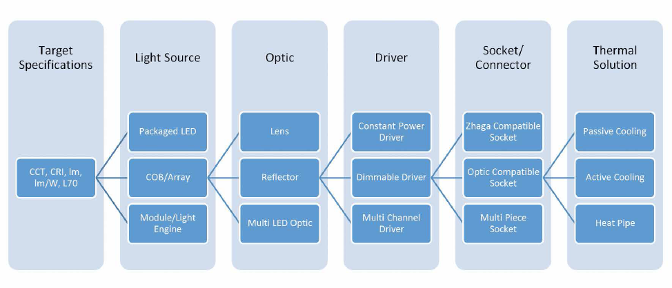
The choices available to the lighting equipment designer, therefore, continually become numerous. This means that there are ever more varied ways of achieving the same design objective. Given any one system specification, the number of potential combinations of components that could meet the specifications is significant and increasing steadily (Figure 1).
The overabundance of design options is creating the need for some form of design automation to accelerate and simplify the selection of components. A software tool can also enable the designer to pose ‘what if?’ questions in order to quickly compare the benefits and trade-offs of different component choices and configurations. Until now, the LED lighting market has responded to this need for decision support tools by releasing component-based online simulation or selection tools. However, these tools are insufficient because they only process a single lighting component at a time (i.e. only the LED from the LED vendor’s tool or only the optic from the optic vendor’s tool or only the driver from the driver vendor’s tool) and not the lighting system as a whole. Figure 1: Multitude of design options for meeting the same target specifications
The Current Tools and Design Process
Regarding existing light source simulations tools, the user first selects the light source, then a drive current and a temperature where the tool outputs flux and efficacy values. Some of the more sophisticated versions allow the user to select the light source, a temperature, a target flux and target efficacy where the online tool will calculate the required forward current to meet the target specifications. Unfortunately, the existing light source simulation tools typically force the user to pre-select the light source component, temperature and even at times the drive current where many of these variables will not initially be known to the user. Experienced designers will have an instinctive feel for the number and type of light sources that could meet the requirements, and for the implications the light source choice will have on other system components such as the optic, driver and heat sink. But even the most experienced designers cannot maintain up-to-date knowledge of all the existing and newly introduced components available on the market.
There is a significant difference between selecting a good light source to meet the target specifications versus the optimal light source where the optimal selection will change depending on the target flux, target efficacy, target lumen maintenance, required light source count, optics compatibility, driver compatibility and cost. As an example, the existing online tools do not incorporate LM-80 data where the selected current that will meet an efficacy target in the tool may be too high in some cases to meet the target lumen maintenance. As a result, without the incorporation of LM-80 data in the initial analysis, the user may select the wrong light source where the user may be eventually forced to lower the drive current to meet the lumen maintenance target, which may increase component count and cost where a more optimal approach may have been to select a more expensive light source that can be driven at a higher current to reduce the light source count and total light source cost.
A new type of online design tool is required for the lighting industry that incorporates all the major variables in selecting the optimal light source and the related system components such as optics, drivers, connectors and heat sinks. Furthermore, this new tool must not require information that will generally not be known to the user before he or she runs the simulation such as drive current, temperature, or part numbers. In other words, the workflow of the tool must behave how a lighting designer thinks.
Advanced Design Tools Offer an Improved Process
The LSC [1] is a new type of proprietary online design tool that was developed with the lighting designer in mind. This new online tool significantly increases the lighting designer’s productivity by combining thousands of light sources, optics, drivers, sockets/ connectors and thermal management solutions with a powerful proprietary algorithm to instantly and seamlessly develop luminaire designs. This tool reduces days or weeks of laborious research efforts to a matter of minutes. Every designer typically starts a new solid-state lighting system design with a basic set of requirements: CCT, CRI, flux, efficacy, lumen maintenance, and if applicable, a target optical beam pattern (Figure 2).
 Figure 2: Specifying basic system parameters – the first step when using the Lighting System Creator
The Component Selection Process
Finding the right light source
After specifying the basic system parameters, the process then steps the user through the whole component selection process. This starts with the selection of the light source. The default proprietary algorithm leverages the light source LM-80 data from all candidate light sources to determine the maximum drive current (to minimize light source count and cost) to meet the target flux and efficacy at the maximum in-situ temperature (to minimize the size and cost of the thermal solution) in order to also meet the L70 lumen maintenance target. As a result, the user never needs to pre-select the light source drive current or temperature to start an analysis.
The user will then be presented with a table that lists the light sources separated by technology (i.e. packaged LEDs, COBs & arrays, board level modules, integrated light engines), which meets the requirements described in the Luminaire Target Specifications section. The user can then select the part number of interest by analyzing the trade-offs of different parametric values in the table such as (but not limited to) light source count, number of supported optics, maximum in-situ temperature and cost. It’s important to note that the system also enables trade-off decision from a make or buy perspective as the user will be able to compare packaged LEDs (make), versus module or light engine based solutions (buy), which will reduce the time to market.
Setting Filters
In the downlight design example (Figure 3), the user has decided to filter and show only the light sources that can meet the target specifications with a single light source, which will eliminate packaged LEDs from consideration. The user then selected a COB light source by clicking on the radio button.
 Figure 3: In the Suggested Light Sources section, the user can choose from a variety of light source types that meet the target specifications
Optimizing Design Parameters
Once the light source has been selected, the user is able to edit several parameters (Figure 4 - darker blue cells) such as light source count, drive current, flux bin, forward voltage bin, in-situ temperature and junction temperature where all other parameters will be recalculated in real-time. Furthermore, for multi-light source applications such as troffers where there is often over 100 mid-power LEDs, the user is able to modularize the system by indicating the number of boards that the lighting system should contain. This will then affect the series/parallel configuration of the light source on a per-board level as well as the board-to-board interconnection for the light source driver, which will all be determined automatically.
 Figure 4: Refining the design parameters for the selected light source
From a trade-off standpoint, lowering the in-situ temperature (or junction temperature) will increase flux and efficacy and may reduce light source count but it may also require a larger thermal solution to maintain the temperature at the lower user-centered level. Another design trade-off (for multi-light source applications) is increasing the light source count, where the obvious disadvantage is that it will increase the total light source cost. However, it may provide more flexibility to find a suitable driver by increasing the available series/parallel options and it will increase the range of driver output currents (particularly for programmable drivers) to meet multiple target flux and efficacy requirements within the same design.
Selecting the Other System Components
Optics
The next step in the design process is selecting the system components such as optics, driver, connector/ socket, and thermal solution. The optic is the first system component to select because it has the potential to change the light source if there is no suitable optic for the selected light source. Furthermore, the optic can potentially affect the driver solution if a multi-light source optic is selected as this type of optic may require an adjustment in the light source count to reflect the number of light sources that each optic can support.
The selected application and light source will directly impact which optics will be displayed. In the downlight design example, only symmetrical medium and wide viewing angle optics are displayed (Figure 5) to coincide with the application requirements. The feature to display product and application specific optics significantly reduces the number of optic options to assist the user in quickly selecting the appropriate optic.
 Figure 5: Displaying application and product specific optics
Drivers
Once the optic has been selected, the next step is to select the light source driver. The algorithm supports all types of light source drivers from fixed current, to multi-current to fully programmable drivers where the driver output current will meet the luminaire target specifications (Figure 6). The algorithm considers the entire light source forward voltage bin range and the impact of temperature for displaying suitable drivers. For multi-light source and multi-board applications, also the series/parallel light source connection topology as well as the board-to-board interconnection topology will be shown.
 Figure 6: Displaying compatible driver solutions
The LSC also includes a proprietary driver algorithm that will ensure that a suitable driver solution will be found by automatically adjusting certain design parameters such as the light source forward current while keeping the light source count constant, light source count to increase the series/parallel array options for multi-light source applications and driver count for very high lumen applications, all while still meeting the target specifications.
In order to assist the user in selecting the most appropriate driver, several additional parameters are displayed such as (but not limited to), driver efficiency at full load, light source load percentage, dimensions, driver marks (i.e. UL, CE, CCC, PSE), driver class (i.e. Class 1, Class 2, Class I, Class II) and supported driver dimming signals (i.e. 0-10V, DALI, PWM, Triac). For the downlight example design, the selected driver had the required dimensions (rectangular versus linear) and driver marks to support multiple international markets, which made it an appropriate choice for this particular design.
Electromechanical components
If the selected light source type is a COB, which is the case for the downlight example design, a list of light source compatible sockets will be displayed in the Light Source Accessory section (Figure 7). In some cases, the luminaire designer may want the selected optic to be held in place by the socket itself instead of the luminaire housing where there is a footnote to indicate when this socket/optic combination is possible. However, if the light source type is a packaged LED or a light engine with multiple connector options, a list of board-to-board connectors will be displayed instead of sockets. For the downlight example design, a low profile compatible socket was selected.
 Figure 7: Displaying compatible socket and connector solutions
Thermal management solution
The final system component is the thermal management solution where options that maintain the in-situ temperature to meet the L70 lumen maintenance target are suggested while ensuring that the light source will mechanically fit onto the thermal solution. Both passive and active thermal solutions are supported. For multi-board scenarios, the user will have the choice to select a single thermal solution for all boards or a thermal solution for each board for a more modular thermal design approach.
A key parameter for selecting the thermal solution is whether there are existing mounting holes that are compatible with either the selected socket or the light source itself. Availability of compatible mounting holes is often a deciding factor for a lighting designer to consider a standard thermal solution versus a custom one. As a result, for the downlight example design, a passive circular heat sink with compatible mounting holes was selected (Figure 8). The user can then generate a comprehensive Excel report of all the lighting system design choices to review with his or her peers and manager to obtain approval to begin the prototyping stage.
 Figure 8: Displaying compatible thermal management solutions
Conclusions
Developing a luminaire requires the designer to manage and optimize the complex interdependencies of the light source and all other system components. Due to the highly competitive nature of the lighting industry, it is becoming increasingly important to make optimal design decisions to meet both performance and cost targets. Furthermore, it’s critical that design choices are made quickly and effectively in order to reduce the time from conception to the launch of new products in order to gain market share.
For the first time, the Lighting System Creator [1] gives designers the ability to adopt a system configuration tool which thinks the way they do.
References:
[1] www1.futurelightingsolutions.com/lsc
