Electrical Over Stress - How to Prevent an LED Failing Earlier than Expected
Article from LpR 66, page 70: While LEDS are, in general, very robust, failures still happen due to electrical over stress. Mauro Ceresa, EMEA Field Application Engineer Manager at Cree, will cover all aspects related to electrical over stress, or when an LED fails due to being subjected to a voltage beyond its specification limits. He will explain why the failure occurs and how to prevent this from happening. The article will explain the fundamental aspects of a good PCB layout design and how this is linked to the longevity of an LED.
Solid state light technology has become an important player in the lighting industry thanks to the many performance advantages that LEDs offer. The performance enhancements of this rising star technology - its efficiency advantages in particular – have led to many new applications and the widespread adoption of LED.
Solid state light usage proliferation exposes LEDs to a range of new and harsh working conditions, and demonstrates that their theoretical “great longevity” could easily be compromised by various environmental factors. Chemical incompatibility is one of the first issues customers face, but luckily, in most cases, this problem tends to become apparent quite rapidly when caused by a fixture design fault.
The speed at which these faults become evident means that the industry is becoming increasingly conscious that the expected lifetime of LEDs could be seriously compromised if they are exposed to volatile substances incompatible with solid state light constructing materials. Unfortunately, not all threats to LEDs are evident enough so as to enable users to take the necessary steps to fix the issue before a massive field failure occurs.
The most critical threat comes from the same source that powers the LEDs, and is known as “Electrical Over Stress” (EOS). An EOS occurs every time the LED driving current or voltage exceeds the component maximum rated values. There are many different types of EOS - some are generated during the LED assembling or testing process, while others are produced by the power supply or come from the environment induced by the electromagnetic field.
An EOS is the most dangerous threat for solid state light technology because it uses the same path used to light up the LED. In addition, the damage it causes is often not immediate. In many cases, the LED may only cease to work days or even months after installation. These two characteristics of an EOS mean it can be incredibly difficult to prevent, and expensive to solve. The time lapse between the EOS occurring and the failure to detect the fault can be quite long and have serious repercussions as more luminaires may be produced and installed, thereby increasing the cost of warranty replacement.
Why an Electrical Over Stress Happens
There are many different reasons and ways in which an EOS could happen, but there is only one result: LED failure. EOS damages the LED chip structure which causes it to fail faster than its expected lifetime.
An EOS is caused by external sources like the working environment, a test procedure or human interaction, as well as an internal interaction like bad or wrong power supply, PCB design layout, or faulty components that generate a voltage or current across the LEDs exceeding the maximum voltage rated in the datasheet.
When the voltage or current exceeds the component maximum rated values, this is called “stress”. To better understand why an EOS happens – in both an open or short circuit - and the time it will take for the LED to fail, it’s important to consider the energy content of the stress. Every time a stress is applied to a solid-state light product, it creates a voltage and a current which flow through the entire circuit impedance (fixture plus environment). This means a certain power stress is applied to the LEDs.
If the power stress signal is integrated, over time the energy stress will be measured in Joule. Low energy stress generates insignificant damage - or sometimes none at all - while mid-energy stress damages the LED, but failure will only occur a long time afterwards. On the other hand, high energy stress immediately causes the LED to break either by blowing up the wire bonds, or melting the die attached to the solder pads.
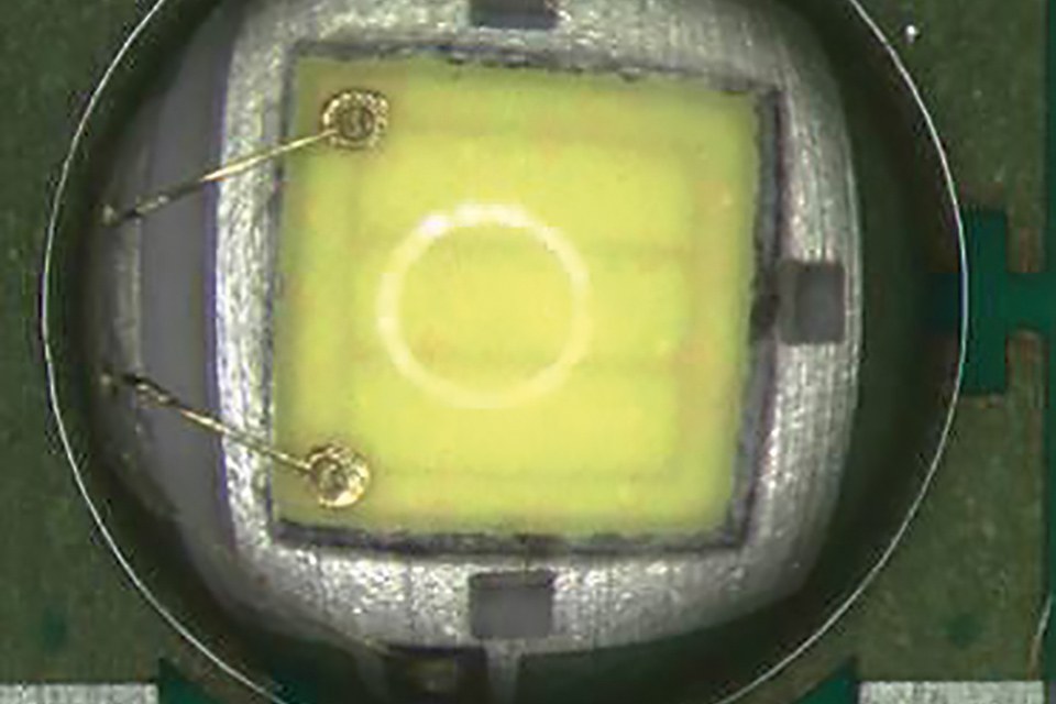
It’s important to note that even without a failure after a stress, this does not mean the LED is not damaged. Low and mid energy stresses could lead to micro damages (Figure 1) that are not instantly visible (Figure 3), but these can end in catastrophic failure after a number of working hours. That is why every LED that is exposed to an electrical over stress should be considered a device at risk of failure.
 Figure 1: Low and mid energy stress generate a long term short circuit failure due to micro damages
 Figure 2: High energy creates an immediate failure in open circuit
 Figure 3: LED with invisible micro damages
Different Types of Electrical Over Stress and How to Prevent Failures
There are many possible sources of EOS that could be generated by fixture design issues, human error and even by the limitations of regulations in place before the solid-state light technology broke into the lighting industry.
The following will cover all the potential circumstances that can cause an EOS, and provide guidance and recommendations to prevent field problems. In some cases, the solutions are strongly influenced by customer design, which is why it is essential for LED manufacturers to work closely with customers to ensure their fixture designs are EOS-proof.
Electrostatic discharge
The first possible source of EOS is generated by operators handling the LED or printed circuit boards. This type of EOS is generated by the Electro Static Discharge (ESD). An ESD is a low-energy event with a very short duration – it only lasts a few microseconds. An ESD is typically generated in non ESD protected working environments. For instance, the operator body could have a very different electrical potential from the LED board, and when they come into contact with LEDs, an ESD can occur.
Typically however, ESDs are not a problem for LEDs because the majority of LEDs are equipped with an ESD suppressor which protects the LED chip. Nevertheless, some very small new LEDs which are designed to maximize light density, are not equipped with ESD suppressors, which is why an external ESD suppressor must be used. These additional components have to be positioned very closely to the LED to protect it properly. These ESD suppressors have been used for decades to protect other electronic devices, and can be used to solve this possible EOS issue if needed.
Power supply
Another possible source of electrical over stress comes from the power supply used in the luminaire. There are several possible conditions that could damage the LEDs even in the absence of any misoperation by the user. Every time a new constant current power supply is selected, it is mandatory to check output tolerances, current ripple, transient spikes during the switch on and off phase and finally, the hot plug current. Tolerances, ripple and spikes could be silent LED killers that are compromising the component integrity without any obvious sign. Figure 4 shows a commercial constant current 1050 mA power supply, representing many possible sources of EOS.
 Figure 4: Ripple of a commercial constant current 1050 mA power supply, representing many possible sources of EOS
First and foremost, every time a solid-state light fixture is switched on, this power supply generates a spike of 2 A per few milliseconds. If the LED type used here is rated 2 A or more, there shouldn’t be a problem. However, if the devices used have a maximum rated current of 1.2 A, on a constant current 1.05 A power supply, one could be running a big risk.
If the fixture will be switched on and off once or twice a day, the LED will most probably last as long as expected. However, in cases where a presence or movement sensor turns our fixture on and off, the many spikes per hour will stress our LED, thereby compromising its lifetime.
Another critical aspect of this power supply is the ripple. Here, there is approximately ±40% of ripple. Beyond a few potential unpleasant effects, like flickering and flux reduction, this ripple could force the LED to work out of specification and under stress for continuous, repetitive cycles.
As discussed previously, if using a 2 A or higher rated current LED type, nothing will happen. However, with a 1.2 A maximum current device, the LED lifetime will be seriously compromised by the constant current power supply. It is also essential to consider the tolerance of the average current output, which can worsen the situation, by increasing all these values by the tolerance percentage.
To prevent EOS failure in the scenarios described above, it’s important to use power supplies with a limited transient peak during the switch on and off phase. These power supplies must not exceed the maximum rated current of the LED. Moreover, the typical current combined with the ripple and the positive tolerance must not exceed the maximum LED rated current. If all these conditions are respected, the power supply will not lead to any EOS.
Another possible source of failure is the reverse polarity connection of the power supply, or negative pulses. If an operator swaps the polarity during the test or production phase, the LED will be seriously damaged by this EOS. To prevent this from happening, it is good practice to use power supply with short circuit protection and equip the LED board with a diode in parallel to the LED string in reverse polarity. If the power supply is connected to the LED board with a connector, a polarized connector is the best solution.
One last test - which is always good to run - it is a “destructive test” on few LED boards to measure the hot plug current. This test consists of switching on the power supply (without connecting any LEDs) and then hot plug to the LED board. By doing this, the hot plug current peak can be measured (Figure 5) that represents the possible electrical over stress in case of bad or wrong electrical contact during the luminaire assembly or test. The peak as seen on Figure 5 is proportional to the difference between the power supply maximum voltage output without load, and the total forward voltage of the LED string. This means that the higher the gap, the higher the probability of LED damage induced by a misoperation or bad electrical contact.
 Figure 5: The “hot plug current peak” test represents the possible overstress and the probability of LED damage induced by a misoperation can be estimated
To prevent EOS failures induced by the hot plug current, it is important to follow assembly procedures that exclude potential hot plug scenarios and choose appropriate power supply and connectors.
During the assembly process, the power supply must not be plugged into the electricity before the LED board is firmly connected. Moreover, the LED board must not be disconnected from the power supply before the power supply has been turned off. Using a power supply with a built-in current limiter would also make the assembly operation safer, while also preventing any potential human error.
Finally, connector quality is crucial. Poor quality connectors with a loose electrical contact, act as a hot plug - even if the board is electrically connected to the power supply. Generally, if the LED produces flashes or blink light, a current pulse is likely to be behind it, which could be a sign of an EOS and will require further looking into. By following these simple rules, any possible EOS during the assembly operations can be avoided.
Tests
Other potential production operation issues that can generate electrical over stress include in-circuit and laboratory tests. These tests present a high potential for EOS – and hot plug EOS in particular.
In-circuit tests tend to be automated processes and can be useful when done properly. In order to avoid the risk of EOS, it is essential that the machine software carrying out the test is programmed to follow this step-by-step process: First and foremost, connect the probes; apply the energy to the test circuit; remove the energy from the circuit and finally, remove the probes contact. By following this process, the driving circuit will successfully test the LED without causing any damage.
In order to ensure that a software bug does not damage the LED, the best option is to use a constant voltage source with a resistor in series to limit the test current. This type of test cannot be conducted when measuring the LED flux, CCT and Vf, as the forward voltage variation from LED to LED could influence these parameters. In all the other cases however, it is a very safe way to in-circuit test LEDs.
Laboratory tests are more critical, as boards are usually tested manually and the potential for human error is very high. In some cases, constant current power supply is used, while in others, laboratory power supply with current limiters is the preferred customer choice - both of which are very dangerous. In the case of constant current power supply, if the sequence is not done every time perfectly the LED will be damaged, whereas in the second case, there are a number of variants that could damage the LEDs.
When using constant current power supply, it is recommended to put two push buttons on the cord that connect the power supply to the plug. By doing this any operator - even an untrained operator – will be forced to connect first the LED board to the power supply and then push down the two buttons.
Even if the power supply is plugged in, the primary stage is not electrified by the two push buttons that are opening the circuit. It would be possible to run this test with just one button, but installing a second saves the operator from pushing the button while simultaneously connecting the board with the other, and just ensures a safer process.
When using laboratory power supply with a current limiter, there are two main risks – the first being simply that someone might involuntary move one of the knobs, causing the LED to stress due to the change of setting. The second risk lies in that the power supply is constantly running, and the output stage is energized and if the current limiter circuit is positioned before the output capacitors, the current limiter will begin working once the LEDs are already damaged. Despite this being perceived as a very safe LED test mode, it is not.
Field hot-plug and long cables
But solid-state light fixtures are not designed to just be kept in warehouses, and many EOS risks exist beyond the production phase. This is why technicians aim to anticipate potential EOS triggers once a fixture is installed. For outdoor applications, this means considering different weather conditions and electromagnetic fields, as well as on/off cycles and other induced magnetic fields for indoor applications.
Today, the majority of LED fixtures are equipped with an on-board driver which protects against hot-plugging during the installation phase. In the early LED adoption era, the three LED MR16 lamps were destroyed during the installation phase by hot-plugging. Having the driver on board or together in the fixture housing also prevents EOS caused by the long cables that connect the LED boards to the power supply, and act like antennae. They connect all the electromagnetic fields produced by radio systems, lift motors, etc.
In some cases, customers position a Transient Voltage Suppressor (TVS) on the LED board to prevent this type of EOS and hot plugs, but this is not effective for two reasons. Firstly, these EOS are high frequency signals that bypass these suppressors, and secondly, the electrical characteristics of the LED and the TVS do not match.
Figure 6 shows a series of 12 LED “typical” and “maximum” forward voltage. The TVS should be selected with a minimum breakdown voltage greater than the maximum LED forward voltage at the maximum driving condition. This is essential because the TVS parallel to the LED string must not absorb any power in standard working conditions.
 Figure 6: Badly designed Transient Voltage Suppressor that never protects the LED as it does not cross the LED curves
In Figure 6, the green TVS curve never crosses the LED curves, which means that the TVS will never protect the LED. Instead, the LED absorbs the entire EOD.
We will explore in detail how to design a circuit to protect against common mode or differential mode EOS, but first the best PCB design will be discussed.
PCB design
To avoid any potential dangerous conductive path between the fixture housing or heat sink and the LED pads, it is very important that the Printed Circuit Board (PCB) be designed to keep an appropriate creepage distance from the copper pads and the edges of other metal parts connected to the housing. In Figure 7, any copper path close to the edge must be kept over the insulation distance. The minimum suggested distance is 3 mm, even though the recommended distance is generally anything from 5-7 mm when feasible.
Another critical consideration of PCB design are the copper traces close to the screws. The distance must be calculated considering the screw head diameter and not the PCB hole. When wires are fused on the PCB instead of using the connector, it’s very important that the cable wire insulation covers the soldering pad and does not reduce the creepage distance.
PCB used for LED boards is typically aluminum-based. The aluminum and copper are separated by a dielectric material that provides the electrical insulation between both metals. This dielectric should be thin enough to guarantee a good thermal transfer from the LED to the fixture housing, but thick enough to provide sufficient electrical insulation. Normally the PCB aluminum is in direct contact with the fixture heat sink, so the unique insulation is guaranteed by the PCB dielectric. For this reason, it is crucial that the PCB vendor guarantee the minimum value of the PCB breakdown voltage for all the PCB supplied.
If any of the creepage distances or the PCB breakdown voltage is not sufficient to withstand the environment surges, there is a risk that electrical arches and discharges will occur and the LED will be stressed and damaged by an EOS (Figure 7).
 Figure 7: If any of the creepage distances or the PCB breakdown voltage is not sufficient, the risk for damage by an EOS is very high
Common and differential mode surge
Most LED users will probably be familiar with the scenarios outlined above. Before exploring further situations causing EOS, it’s important to understand industry regulation and protection classes.
The International Electrotechnical Commission (IEC) and the IEC61140:2016 define the rules of protection for people against electric shock. Depending of the country and the type of product, there are different insulation level requirements for the devices sold in each market.
The most commonly-used insulation classifications are Class I and Class II. Class I fixtures must have their housing connected to the electrical earth with a dedicated cable. Class II fixtures on the other hand, are designed to provide the required level of safety without any electrical earth connection.
|
Protection Classes Symbols |
|
|
Class I |
Class II |
|
|
|


Table 1: Protection classes symbols
These two different classifications make the solid-state light fixture behave in a completely different way when exposed to environmental stresses. In general, if the electrical earth connection is done in an effective and reliable way, the Class I luminaries suffer less from EOS failure but in reality, both luminaire types need to be designed efficiently to prevent EOS damage. Another crucial regulation to consider is the IEC60598-1:2014 that defines the general requirements and tests for luminaries, including the solid-state light fixtures. This 2014 edition replaced the 2008 version, and provides a relevant change for Class II products.
Paragraph 10; Section 4 of IEC60598-1:2014 on “Construction”, addresses the double insulation Class II luminaires. Sub-paragraph 4 (IV.10.4) of the chapter specifies the protective impedance device, stating that accessible conductive parts separated by double insulation may act as a conductive bridge using resistors or Y2 capacitors. They need to consist of at least two separate components of the same rated value.
These components must comply with appropriate IEC regulation. With Class II luminaires, it is possible to add specific components connecting LED boards to the fixture body. This makes it possible to analyze what the LED circuit looks like during fast transient stress. Figure 8 shows two LEDs in series with a simple model that shows the LED and the ESD protector built-in in their package. This model does not consider all the parasitic components or the influence of the LED thermal pad. The thermal pad is a vital pad that allows the LED to efficiently transfer the heat from the source (junction) to the air via many metal parts.
 Figure 8: A simple model of two LEDs in series with an ESD protector
For a very good thermal transfer, the thermal pad should be connected to a very large copper area on PCB. This spreads the heat horizontally and then efficiently transfers it vertically to the aluminum layer of the PCB, thanks to the large transfer area. Two metals separated by an insulator create a capacitor, which means that PCBs are capacitors that should be considered in this particular analysis. This parasitic capacitance could be big or small depending on the PCB design and the material used. It cannot be ignored and it is important to understand how to manage it in order to avoid EOS problems.
LED and TVS could be modeled in very complex way, and for people who enjoy spending hours in simulations, this is a great way to have fun. For the purpose of this paper, just a simplified model with the capacitor connected electronically in parallel to the other components is used, as illustrated in Figure 9. Because of the parasitic capacitance between each thermal pad to the ground, it’s important to understand how to connect them. There are two options: Leave them separate or connect them.
 Figure 9: Simplified model of an LED and TVS with a capacitor
There is also is the option to leave them electrically floating or to connect them to an electrical voltage potential. Leaving them floating is a relatively unsafe option, as any common mode stress is applied directly between the thermal pad and the LED electrical pads - anode and cathode. This creates a fatal EOS as soon as the voltage drop between the points marked by the blue arrows (Figure 10), exceed the LED package insulation. With regards to the LED package material, ceramic provides much better insulation than plastic, and depending on the distances between pads, it’s possible to have a package insulation voltage ranging from a few tens to hundreds of volts. In any case, common mode signals could reach easily thousands of volts, thereby generating an electrical over stress to the LEDs.
 Figure 10: Leaving LED and TVS floating is a relatively unsafe option
Connecting the LED thermal pad to a voltage reference protects the LED from EOS generated by common mode voltage stress. The signal follows the path towards the earth, via the thermal pad parasitic capacitance, and the voltage across the LED package is limited. Now the need to connect the thermal pad to some electrical potential is clear, but there is still the option to keep them separate or connect them all.
Figure 11 shows the circuit of the luminaire stressed by a differential mode. The red arrow shows the direction of the stress signal on a positive surge, while the blue arrow is on a negative surge. For the purpose of this discussion, the thermal pad’s connection to the anode as well as its connection to the cathode will be covered.
") Figure 11: Luminaire stress caused by a differential mode (red arrow shows the direction of the stress signal on a positive surge, while the blue arrow is on a
Figure 11: Luminaire stress caused by a differential mode (red arrow shows the direction of the stress signal on a positive surge, while the blue arrow is on a
negative surge)
In the case of a positive surge and the thermal pad is connected to the anode, the stress will be split between the standard path through the LED string and the parasitic capacitance between the thermal pad and the earth. The split ratio is determined by the impedance ratio of the LED path towards the earth and the first parasitic capacitance of the thermal pad. It is evident that by connecting the thermal pad, the parasitic capacitance is n times bigger (where n is the number of LEDs), and the impedance is n times smaller – absorbing a big part of the stress.
This means that it is better to connect all thermal pads than leaving them separate. In case of a negative stress signal, the entire signal will pass through the CLED, polarizing the LED in the reverse way. The impedance of CLED is quite high – and therefore the reverse voltage drop will be quite high too. The ESD TVS contributes to clamping the signal, but because the stress is more in the mid-range energy, the LED is EOS damaged by this reverse polarization.
When the signal occurs after the first LED, it finds the thermal pad parasitic capacitance to reach the electrical earth. Other LEDs on the string become stressed, but less and less so, as each C thermal pad on the series absorbs part of the stress signal.
When the thermal pads are connected to the cathode, the positive stress totally passes through the first LED, damaging it more than in the previous case with the anode connection. However, in the event of negative stress, the last LED of the series is less stressed.
Thanks to this first analysis, the LED thermal pad should be connected all together and then connected on anode for positive stress, and on cathode for negative stress. It is not possible to know which type of stress (positive or negative) a luminaire is facing; therefore the best configuration is a symmetrical one which divides the LED string in two groups with a mirror configuration (Figure 12). The thermal pad of the LED on the positive side must be connected to the anode, and the one on the negative side, must be connected to the cathode.
 will occur") Figure 12: Dividing the LED string in two groups with a mirror configuration is the best configuration as one does not know which type of stress (positive or negative) will occur
Figure 12: Dividing the LED string in two groups with a mirror configuration is the best configuration as one does not know which type of stress (positive or negative) will occur
To improve the protection of this strong solution even further, two additional capacitors CP and CN on positive and negative LED groups are added. The thermal pad areas and CP and CN must be designed and selected properly, but this is possible only when working on a physical customer circuit. One must not forget that IEC 60598-1:2014 allows to use proper components to connect the luminaire body to the positive or negative terminals of the power supply output. This will further reduce the potential EOS impacts on the LEDs.
Conclusions
A number of conditions can generate EOS, which is why they are still the main cause of LED failure before the end of an LED expected lifetime. The reasons for EOS are complex, and the operations and variable conditions that can lead to an EOS are multiple.
The above explores all the possible harmful conditions and summarizes the measures to be taken during the luminaire production process and at circuit level, to make each solid-state luminaire safer and long-lasting.
