Guidance on Specifying Solid State Lighting Luminaires
Certification marks of renowned test institutes are useful tools for end users to easily estimate the quality of a product. They are also a good marketing tool for manufacturers to generate user trust and confidence in a product or the brand. The authors, Jaap Nuesink and Michael Schoof from DEKRA Certification B.V. explain what is needed and which parameters have to be covered in order to be certified, ending up in a guideline of how to qualify for the DEKRA Solid State Lighting Certification Mark.


DEKRA Certification introduced a performance mark for solid state lighting products in 2011, but the high level of initial interest did not translate into certifications. Therefore, at the end of 2012, a survey among OEMs and end users has been conducted to discover the reasons why. The outcome was clear: a performance mark is required, but its program must be better aligned with market needs. Consequently, a solid state lighting forum to explore those market needs together with several manufacturers and end users was established. This process ultimately resulted in a guide to specifying solid state lighting.
Introduction
The guide promotes the use of a standard datasheet which lists the most important parameters for Solid state lighting from the perspectives of OEMs and end users. The parameters are divided into four main groups - namely photometric, electrical, environmental and lifetime - and they are presented in a clear and logical order on the datasheet to enable products to be compared quickly and easily.
Photometric Data Parameters
- Luminous flux
- Efficacy
- Color temperature
- Color coordinates
- Color consistency
- CRI
- Light distribution
System-level specification
Many specification sheets currently available on the market begin with various assumptions. For example, the luminous flux of a module is specified while the losses in the luminaire are not accounted for. In addition, efficacy is often based on the LED modules alone instead of on the full system. To prevent such misinterpretations or misleading data, a quick and easy-to-understand guide on how to specify the efficacy and the luminous flux has been set up. All parameters, including color temperature and color coordinates should be specified under operating conditions and the temperature of the full system should be stabilized.
When taking these measurements, it is important to take into account any potential elevated ambient temperatures as they are specified in the environmental conditions section of the datasheet.
Please note: the ErP directive requires a label showing the efficacy of the light source, which is based on light source measurements. In the case of a solid state lighting luminaire, efficiency can be based on the luminaire. In the ErP directive system-level measurement is not required; however, removal of all elements of a luminaire that could lead to light losses is prermitted - such as the translucent covers, reflectors, etc. - until only the bare, functional part of the luminaire remains. This can be the LED module, cooling and driver system alone. Although this is acceptable practice according to the ErP directive, this does not give the efficacy of the complete luminaire and could thus lead to false conclusions and underperformance of products/installations.
Color coordinates and temperature
There are several reasons why the color coordinates and the Color Temperature (CCT) should be specified.
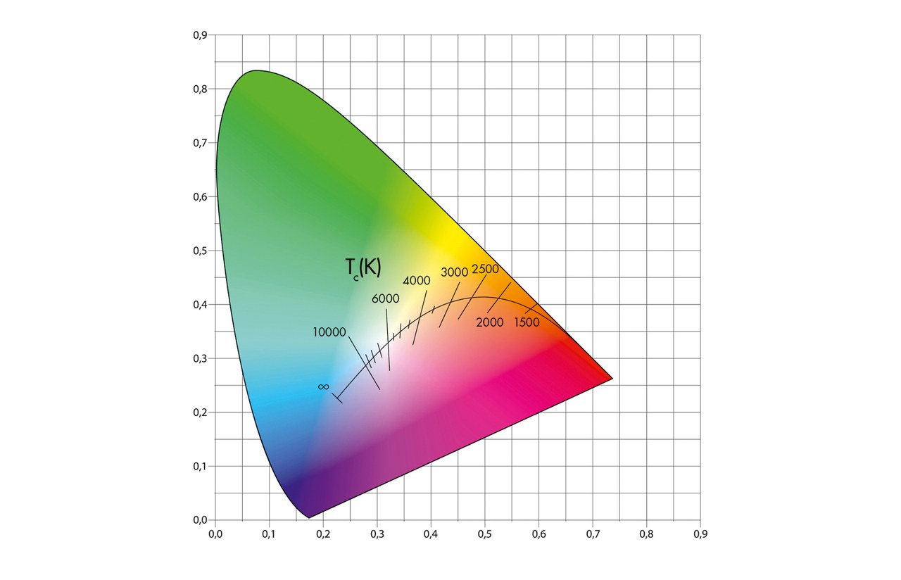
It is necessary to specify both because the color temperature is not defined as a single point in the color space. The CIE has defined the areas close to the Planckian locus where the same CCT can still be used. As a consequence, the color point does not have to be right on the Planckian locus but it can also be in the proximity.
Needless to say, this poses a real problem when specifying different light sources from different manufacturers - and sometimes even different light sources from the same manufacturer - especially in the case of extending or renewing sources in an existing installation. Specifying color consistency requires specification of the actual, exact color point. Another advantage is that the specification sheet can be used to indicate not only white light luminaries, but also every type of colored light fixture. In this case only the color coordinate and its consistency are specified, and not the color temperature.

Figure 1: The CIE x/y color space with the Planckian locus and CCT values
The main references for photometric parameters:
- LM79
- IEC62612
- CIE84
- CIE15
- LM82
Photometric code
A photometric code and is it relevant when comparing products. The code is a six-digit number that contains information about the light quality of the source and its behavior over time.
The values and when to use the photometric code
The code gives an approximation rather than exact values, but that in itself is not necessarily a problem and will mainly depend on the actual application.
The main factor to take into account is the estimated lifetime of the installation, bearing in mind that the code specifies values for up to 6,000 hours. In many cases this is a very low number for solid state lighting and may not prove useful if the lifetime is as much as 10 times this value.
Format and meaning of the standard photometric code XXX/XXX (123/456):
- The first digit (1) indicates the
initial CRI value of the source - CRIcoderange:
6 57-66
7 67-76
8 77-86
9 87-100
- The second two digits (23) indicate the initial CCT value:
- The value is obtained by dividing the actual CCT value by 100, e.g.
3000 K = 30 or
2700 K = 27 or
5600 K = 56 - The first digit behind the forward slash (4) indicates the initial spread of chromaticity coordinates:
- The number is given in MacAdam ellipses, which is an indication of the spread in color between different light sources from the same make and type, e.g.
1 = very narrow > no difference between sources
2 = narrow > potentially very little differences between sources, etc. - The second digit (5) after the forward slash indicates the maintained spread of chromaticity coordinates:
- Thisnumberisalsogivenin MacAdam ellipses and explains more about the spread in color measured after 25% of the actual lifetime (with a maximum of 6,000 h)
- The third digit (6) after the forward slash indicates the maintained luminous flux:
- This value is determined after 25% of rated life or 6,000 h
Examples:
930/339, or 827/358
Electrical Data Parameters
- Rated Voltage
- Rated Input
- Rated Frequency
- Power Factor
- THD
- Surge Protection
- Run-Up Time
- Inrush Current
The first three parameters are self-explanatory.
Power factor
The power factor: there are several points to take into account. The European power factor requirements are laid down in two different directives.
European power factor requirements:
- The EMC directive:
- Products with power > 25W: required minimum power factor ≥ 0.9
- Products with power < 25 W: no requirement
- The ErP directive for products with power of less than 25 W:
- 0 - 5 W: no requirement
- 5 - 15 W: required minimum power factor 0.4
- 15 - 25 W: required minimum power factor 0.5
The requirements for all products below 25 W are very low power factors resulting in not very efficient installations. Moreover, many tenders specify higher demands. Hence, a higher power factor can be a sales argument for luminaire manufacturers.
THD
THD (the harmonic distortion) is a percentage that indicates the distortion the system causes on the net, and hence should be limited. THD and power factor are closely linked in practice.
Surge protection
Surge protection is the capability of a system to protect itself against sudden spikes in the net. The requirements, which are set out in the EMC directive for drivers, were relaxed recently. Spikes can lead to situations in which the surge protection of drivers is no longer sufficient to protect the luminaire. This was not a big problem in the past with conventional control gear, but today’s increasingly electronic control gear is more vulnerable to these effects. Therefore, more and more OEMs are fitting a separate unit in the luminaire to prevent damage and costly aftersales maintenance.
When surge protection is typically a problem
- In areas with aboveground supply systems. Such systems are characteristically more susceptible to discharges than underground systems
- In areas with heavy industrial activity:switchingonandoff contributes to main disturbances, creating fast transients
Run-Up Time
Run-up time is the actual time it takes before the luminaire produces light, i.e. the speed with which it responds to an action (e.g. flip of the switch). The slight delay is due to the driver, which needs time to start up. Although this may not be relevant in some areas, in other applications users expect something to happen almost immediately after their action. For example, if no light is produced within a minimal timeframe after the switch being flipped, users may think the luminaire or switch is defect.
Inrush Current
The current specification contains two different values for the inrush current.
Inrush current values:
- The maximum current the driver is taking out of the net, measured in amperes
- The number of luminaires that can be connected to one single fuse. For example: a D-type fuse, 16 A, can only serve a certain number of identical luminaires because the inrush current can cause a problem when switching on several fixtures at the same time. This has already caused problems in public lighting applications where installations had not been adapted to cope with the high inrush currents, resulting in malfunctions and all drivers having to be replaced. As a rule, a well-designed system specification should take into account the potential inrush currents that can occur.
The main references for electrical parameters:
- EN60598- 1
- EN55015
- EN61000- 3- 2
- EN61000- 3- 3
- EN61547
- Directive 2009/125/EC with 1194/2012
Environmental Data Parameters
- Ambient temperature
- IP (ingress protection)
- IK (impact resilience)
Ambient temperature
The ambient temperature is a key parameter, in particular for Solid state lighting products. According to the standard, the ambient temperature for a standard indoor luminaire is 25 ̊C and for an outdoor fixture it is 15 ̊C. These are the values to be taken into account unless the luminaire is marked otherwise. However, these values are clearly not always sufficient for the environment in which the product will be used, such as in spaces with high ceilings and elevated ambient temperatures where the actual ambient temperature at luminaire level can be considerably higher. The effect of this higher ambient temperature is an increased LED module temperature and an increased driver temperature, both of which can seriously affect the lifetime of the luminaire.
Table 1&2: See in the attachment above
Ingress protection
IP values are specified for two reasons: Firstly for actual safety, and secondly to ensure that the product is suitable for use in the intended conditions. For example, street lighting will have to comply with at least IPX3 (rainproof).
Other considerations must also be taken into account. For instance, dust protection should be considered for luminaires that are used out of normal reach or are not easily accessible for cleaning purposes.
This could be IP5X or IP6X:
6 is dust-tight whereas 5 lets in some dust, albeit very little. If the aim is to minimize cleaning, code 6 should be considered. In terms of cleaning the outside of the luminaire, a code of IPX5 or IPX6 can be considered since both are spray-proof.
Please note: since the current IP coding system does not contain a code which denotes that it is safe to clean a luminaire using high pressure, the use of high-pressure washers is not advisable.
Impact resilience
The IK rating denotes the impact resilience, or ‘vandal resistance’, of a luminaire. The IK code is an important parameter when specifying luminaires for use in public spaces.
- EN60598- 1
- EN60529
- EN50102
- L value
- F value
- Driver life
The L value indicates the expected lifetime of a product and the F value indicates the predicted failure rate over that lifetime. Hence, the two values are closely linked and both should be specified based on the information about the solid state lighting module. This gives a clear view of the expected reduction of light output and occurrence of failures over time. The timing should be clearly mentioned on the modules, and the preferred values are linked to the IEC PAS standard as follows: L at 90%, 80% or 70%, and F at 10% or 50%. Many other values are currently still being used in the market, which may cause confusion. More problematically, not all manufacturers publish the complete set of data and, even more significantly, it is not always clear if the module conditions in the luminaire are in accordance with the claim. The key for the luminaire manufacturer is to confirm the conditions for the solid state lighting module in the luminaire.
Please note: a 50% failure rate for a luminaire is not a realistic value to work with. Consider an investment that requires replacement of at least 50% of
the luminaires due to malfunction within the planned operational time. This can hardly be a satisfactory proposition.
The lifetime problems in today’s solid state lighting fixtures are no longer caused by LEDs - if the LED fitting is installed correctly and used in an accurately designed luminaire, it is possible to achieve very long lifetimes. Instead, the main issue is the lifetime of the driver; components that are used to build drivers generally have limited expected lifetimes that can be well below those of the LED modules. In some products on the market that are specified for long lifetimes, the LED module part of the solid state lighting luminaire will not have a problem achieving it but the driver definitely will. A good design ensures that both driver and LED module are cooled sufficiently.

Figure 2: The luminaire data sheet must show the specifications shown in this example of a standard data sheet if they want to use the DEKRA performance mark
Please note: for long lifetimes, it is essential to keep the components as cool as possible and ensure that both LED module and driver have similar expected lifetimes.
- LM80
- TM21
- LM82
- IEC PAS 62717
- IEC PAS 62722
When examining these basic parameters it can be argued that other parameters play a significant role in specific situations. There is no reason to limit the datasheet to the parameters described here, and manufacturers should provide more information wherever it is relevant. This is still a topic of discussion with the aim of preparing further extensions and additional parameters for specific usage cases. One example is the list of parameters for public lighting purposes, where more information is needed and very long lifetimes are important. Furthermore, although the basics remain the same, the environmental conditions are completely different for a luminaire used outdoors than for one for office use.
Conclusions
Of course, the use of the datasheet will help in promoting the quality of solid state lighting. But the new voluntary LED Performance mark adds further value by demonstrating that the parameters have been verified by a certified third-party testing house. The certificate issued to the manufacturer confirms that all parameters are correct and are being monitored through a program of market surveillance and factory inspections.
