Light-Emitting Surface (LES) Concept Enables Comparison of Photometric Properties by Osram GmbH
The concept of the light-emitting surface (LES) has been developed by the Zhaga Consortium to enable comparisons of the photometric properties of different LED light engines. Stefan Lorenz, a Systems Architect with Osram GmbH, describes the theory behind the LES and how it applies to the different Zhaga Books.
The amazing speed at which LED technology is evolving has surprised not only the experts in solid-state technology. This development is a problem to those who need to rely on a certain constancy in light-source design for longer than a year - which is everyone who wants to sustain a lighting solution or fixture for more than that time.
To solve this conflict, the Zhaga Consortium is establishing a set of specifications which separate the internal technology of the light source from external features necessary to maintain a long-term constancy in the application.
Zhaga specifications describe LED light engines (LLEs) and related components including LED modules and LED drivers. These specifications are called “Books” and define certain features of these LLEs and components which are needed to keep them interchangeable.
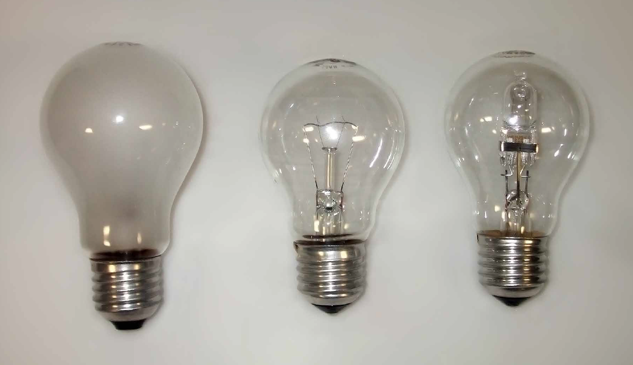
This article deals with the concept of the light-emitting surface (LES), as it was developed by the Zhaga Consortium. LES is designed to enable the easy evaluation of the optical emission of an LLE or LED module without reference to its internal technology. i.e. the outer envelope of the lamp. Middle: A light engine with a small LES, using standard filament technology. Right: A light engine with a small LES, using halogen technology. All three light engines are compatible in most luminaires made for them") Figure 1: Three „classic“ light engines that share common mechanical, electrical, and optical properties. Left: A light engine with large and homogeneous light-emitting surface (LES) i.e. the outer envelope of the lamp. Middle: A light engine with a small LES, using standard filament technology. Right: A light engine with a small LES, using halogen technology. All three light engines are compatible in most luminaires made for them
Figure 1: Three „classic“ light engines that share common mechanical, electrical, and optical properties. Left: A light engine with large and homogeneous light-emitting surface (LES) i.e. the outer envelope of the lamp. Middle: A light engine with a small LES, using standard filament technology. Right: A light engine with a small LES, using halogen technology. All three light engines are compatible in most luminaires made for them
Compatible and Interchangeable
The ability to interchange LED light engines in one luminaire doesn’t imply that one will get exactly the same behaviour with all LLEs. This becomes obvious if you think about substituting a 100 lm/W LLE with a 130 lm/W LLE, for example. The new LLE will result in a more energy-efficient luminaire assembly, of course.
Figure 1 shows an example of “well-known interchangeable light engines”, which have different technologies and light-emission characteristics.
Zhaga defines two degrees of similarity that two (different) LLEs can achieve in a certain luminaire. The basic degree is “compatible”; two LLEs are said to be compatible if they have similar mechanical, thermal, and electrical properties. In other words, they are compatible if they fit into a luminaire designed for this type of LLE, and if they can be operated. The examples in figure 1 are compatible in the Zhaga sense.
The more advanced degree of similarity between LLEs is “interchangeable”. This term includes “compatible”, and adds, on top, a comparable photometric performance. Thus, in order to evaluate interchangeability, a suitable description of photometric properties is needed.
The Light-Emitting Surface
The primary concept developed and used by Zhaga to judge comparable photometric properties in different LLEs is the light-emitting surface (LES). This characterises the area and position of light emission from an LLE in a general way, so that the balance is kept between independence of technology and easy evaluation of similarity in the application.
Unlike classical light sources (such as those in figure 1), normal LLEs do not emit light in all directions. So the first requirement for two LLEs to be interchangeable is that the light emission takes place at a comparable position on each LLE, and in a comparable direction. The rough shape of the emission area should also be comparable. Two LLEs with a similar LES then should produce comparable photometric properties in a luminaire.
The LES of the middle and right-hand bulbs in figure 1 are quite similar in shape and light-emission direction, while the left-hand bulb’s LES has a completely different shape. The typical application of the LLE determines how similar two LLEs have to be for them to be interchangeable. Each individual Zhaga specification defines its own acceptable range. For the figure 1 light bulbs, all three might be called interchangeable as light sources in shaded luminaires, but in open view, the left bulb is not interchangeable with either of the others.
The basic idea of the LES is well represented even in the light bulb example: Position, shape and direction of light emission must be similar in a light source to generate comparable photometric properties in a certain application. The LES concept provides an easy method to describe and compare these parameters in abstract specifications and actual light sources.
Beyond the Light-Emitting Surface
Not all optical properties of an LED light engine can be described by the LES concept. Some, like the luminous flux, are better specified separately and independently. Others, like the far-field luminous intensity distribution, are associated with the LLE, but not directly connected to the LES.
The information on full near- and far-field emission of a light source is usually provided in the form of ray files. These contain sufficient statistical information to simulate the optical properties of an LLE by software. They can even contain information on colour (colour over angle as well as colour related to emission position), whereas the LES is a purely intensity-based concept for reasons of simplicity. The disadvantage of ray files - bulkiness and need for computer-based evaluation - is addressed by the LES concept: a simple method to easily compare LLEs of different technologies.
Ideal LES, Actual LES and LES Range
To be independent from a specific implementation, Zhaga has to describe an “ideal” LES for each application. This ideal LES is a simplified geometrical two-dimensional surface, which characterises the ideal location and shape of the light emission in the LLE. It does not need to be an actual physical surface, but is the idealized, simplified area of light emission in an ideal interchangeable LLE.
 is indicated as blue disc. Note that the disc is elevated above the actual LED module’s physical features in this example") Figure 2: A Zhaga Book 3 LED module. The Ideal Light-Emitting Surface (LES) is indicated as blue disc. Note that the disc is elevated above the actual LED module’s physical features in this example
Figure 2: A Zhaga Book 3 LED module. The Ideal Light-Emitting Surface (LES) is indicated as blue disc. Note that the disc is elevated above the actual LED module’s physical features in this example
Figure 2 shows the ideal LES for an LED module according to Zhaga Book 3. The LES has a circular shape, a fixed diameter, and a fixed height above the LED module backplane.
The “actual” LES of an LLE implementation might deviate from the ideal LES in several aspects such as size, homogeneity, symmetry and vertical position (height). The allowed degree of variation from the ideal LES (the LES “range”) depends on the application, and is specified such that all LLEs which are within the allowed variation range will produce comparable photometric outputs in the application.
 LES height range for a Zhaga Book 3 module. The vertical position of the LES can be anywhere in the indicated range (including below the physical surface of the module/LLE). (b) LES diameter range for the same module. The actual LES outer diameter needs to be within the indicated ring") Figures 3 a&b: (a) LES height range for a Zhaga Book 3 module. The vertical position of the LES can be anywhere in the indicated range (including below the physical surface of the module/LLE). (b) LES diameter range for the same module. The actual LES outer diameter needs to be within the indicated ring
Figures 3 a&b: (a) LES height range for a Zhaga Book 3 module. The vertical position of the LES can be anywhere in the indicated range (including below the physical surface of the module/LLE). (b) LES diameter range for the same module. The actual LES outer diameter needs to be within the indicated ring
Figure 3 shows the LES height range and LES diameter range of a spotlight Book 3 module. The vertical position (height) of the actual LES can be within a range around the ideal LES height.
The diameter of the actual LES can be smaller than the ideal LES diameter, down to a minimum diameter. This range is depicted by the ring in figure 3. The outer diameter of the actual LES is required to be within this ring.
Differences from Physical Features
An example of an actual LES is shown in figure 4, for a real LED module especially suitable for narrow beam applications. The top view shows that the LEDs form a non-circular pattern. The LES diameter range is superimposed in blue. The actual LES, which is limited by a circle around the LEDs, is indicated in red. The side view shows the vertical position of the actual LES and the LES range. The actual LES is within the LES range, so the LED module shown here is compatible with other Zhaga LED modules.
 Figure 4: Actual LES shown in red and LES range shown in blue for a Book 3 LED module. Top view: Actual LES is smaller than the maximum LES diameter, but larger than the minimum LES diameter. Side view: Actual LES is above the individual LED domes, and well within the LES height range
Optics Design for LES
The concept of interchangeable LLEs puts a burden on the design of the luminaire optics, if the luminaire’s LLE is meant to be interchanged. The LES is the commonality that an optics designer can expect from the various LLEs that the luminaire should operate with. As a consequence, optics design should not be based on a single LLE, but rather on the ideal LES laid down in the Zhaga specification (Book) in question. Interchangeability at the Zhaga level is then automatically ensured without additional efforts. Further optimization with ray files would be counterproductive, as it would reduce the interchangeability in favour of a single peak design.
Supplementary LES Information
The inner structure of the actual LES can have quite an impact on comparable photometric performance in certain applications. For that reason, some Zhaga Books have extra requirements on the LES.
Extra Information: Zhaga Book 7
Zhaga Book 7 describes rectangular LLEs with an external driver, which are often used in luminaires formerly equipped with linear fluorescent tubes. To allow for a certain degree of versatility, the LES definition in Zhaga Book 7 is minimal, but requires extra information to be provided with each LLE. The only common property of the LES in Zhaga Book 7 is that it is located at the top of the LED module. This is already sufficient for many applications in which Book 7 LLEs are used.
More information on the structure of the LES is given in Zhaga Book 7 by a luminance measurement in a test luminaire (Figure 5). The resulting image gives an impression of the homogeneity that can be achieved with the tested LED module. The user can decide if the appearance of the LLE is suitable for his application.
 Figure 5: Two standardized LES images from Zhaga Book 7 modules, with either sparse or dense LED placement on the LES. Also shown is a typical Book 7 LED module
Additional Restrictions: Book 3 and Book 4
A more detailed specification and some limitations are needed for the high-intensity LLEs in Book 4 and the circular LED modules in Book 3, for example. Here, more specifications on the inner structure of the LES are necessary to ensure that the LLE is interchangeable and works satisfactorily with typical luminaire optics. A minimum size for the LES is ensured as well as the already-specified maximum size. Also, the LES needs to be sufficiently homogeneous to avoid artefacts - especially in strongly directional luminaires.
 Figure 6: Typical Book 4 LED module, showing the maximum LES dimensions
The ideal LES shapes are circular for Book 3 and rectangular for Book 4 (Figure 6). Deviations from the LES can result in unexpected beam shapes. The actual LES can be only a little smaller than the ideal LES size, but at the cost of deviations in the beam shape. The acceptable variation sets the lower limit in the LES range.
The actual LES must have uniform luminance and a high degree of symmetry, to avoid hotspots or asymmetries magnified by the luminaire optics. Both Zhaga Books 3 and 4 require the determination of centre balance and uniformity. In addition, the circular LES of Zhaga Book 3 is evaluated for rotational symmetry, while the rectangular LES in Zhaga Book 4 needs horizontal and vertical symmetry measurements.
All these limitations and measurements are implemented in Books 3 and 4 to ensure that no LLE deviates too much from the ideal LES. All parameters have some range of freedom, which can be exploited to construct actual LLEs, but the sum of all deviations must be small enough to avoid non-comparable behaviour in the luminaire optics designed for the typical LES.
Both Books 3 and 4 have a very well-defined LES, due to the typical application requirements they are designed for. The well-defined LES guarantees that interchange of LED light engines is possible with minimum variation.
Summary
The challenge of defining a technology-independent and simple description of light emission from LED light engines has been accepted by Zhaga. The LES concept is a simple method to ensure photometric comparability of different LLEs. Zhaga Books specify an ideal LES, with an allowed range of actual variations just small enough so that the individual LLEs are still comparable in their application. The actual LES can be easily compared, without reference to the actual LED technology inside the LLE.
Since its introduction by Zhaga, the concept of LES is well accepted in the lighting community as an easy categorisation for the new opportunities of LED lighting.
Remarks:
[1] An LED light engine (LLE) combines one or more LED modules with an LED driver. The driver can either be integrated inside the LLE, or the LED module(s) and driver can be separate from each other. The light-emitting surface (LES) is associated either with the integrated LLE, or with the LED module in cases where the driver is separate. In this article, the terms “LLE” and “LED module” are used interchangeably
