Light Guide Technology for Obtaining a Different Bi-Directional Direct/Indirect Light Emission Pattern
Market requirements ask for a solution for use in suspended light fixtures that will allow the light to be distributed upward, for indirect illumination, as well as downward, for direct illumination. However, existing light guide technology typically produces fairly indirect light and relatively uncontrolled distribution. Brett Shriver, Vice President at Global Lighting Technologies, explains a new approach with individual light extraction features used within the light guide in order to control light in multiple directions and provide the required semi-Lambertian distribution in the downward direction with low glare while obtaining a bat-wing type distribution in the upward direction.
As lighting fixtures convert from traditional semi-Lambertian emitting sources such as incandescent and florescent bulbs to directional LED light sources, there have been significant challenges in distributing the light efficiently where desired. New developments, as well as existing technologies in LED edge-lit light guides, are allowing manufacturers of these lighting fixtures to produce distinct lighting distributions uniformly and efficiently.
LEDs are inherently directional with regards to their distribution and this is amplified when the packaging of these devices includes reflector cups in order to increase the on-axis brightness of the product. When general lighting manufacturers utilize these devices without secondary optics, they produce spotlight type distributions that are not always suitable for the final product. There has also been the necessity to locate individual devices so that the beam angles cover the entire area that the design requires to be illuminated. Many times, this results in the end user observing a non-uniform light distribution (bright spots and streaks) caused by the bright on-axis light. Until recently, manufacturers avoided these issues by adding heavy diffuser plates to limit bright spotlighting and adding strips of LEDs pointed in multiple directions and locations that require illumination. These manufacturers are now finding a new use for light guide technology that has already been developed.
Introduction
For more than a decade, consumer electronics manufacturers have used LEDs to illuminate their devices including LCDs, logos, keyboards and keypads - by utilizing clear plastic light guides in order to distribute the light evenly and uniformly. Due to many of these devices being extremely limited on power consumption, it is important that these light guides are very efficient and cost effective. Unfortunately, however, there is not a direct transfer of technology in order to use these devices in general lighting in most cases. Manufacturers of lighting fixtures have used different metrics and measuring devices that require new testing of LED products. The measurement of consumer electronics light guides is typically based on surface brightness per square meter and life expectancies are based on the average life of the electronics devices. The general lighting industry, however, requires measurement of the total light being projected from the fixtures into a room or onto a table or other objects while life expectancies are much longer due to expectations that fixtures are not quickly replaced or obsoleted in the manner as consumer electronic devices are.
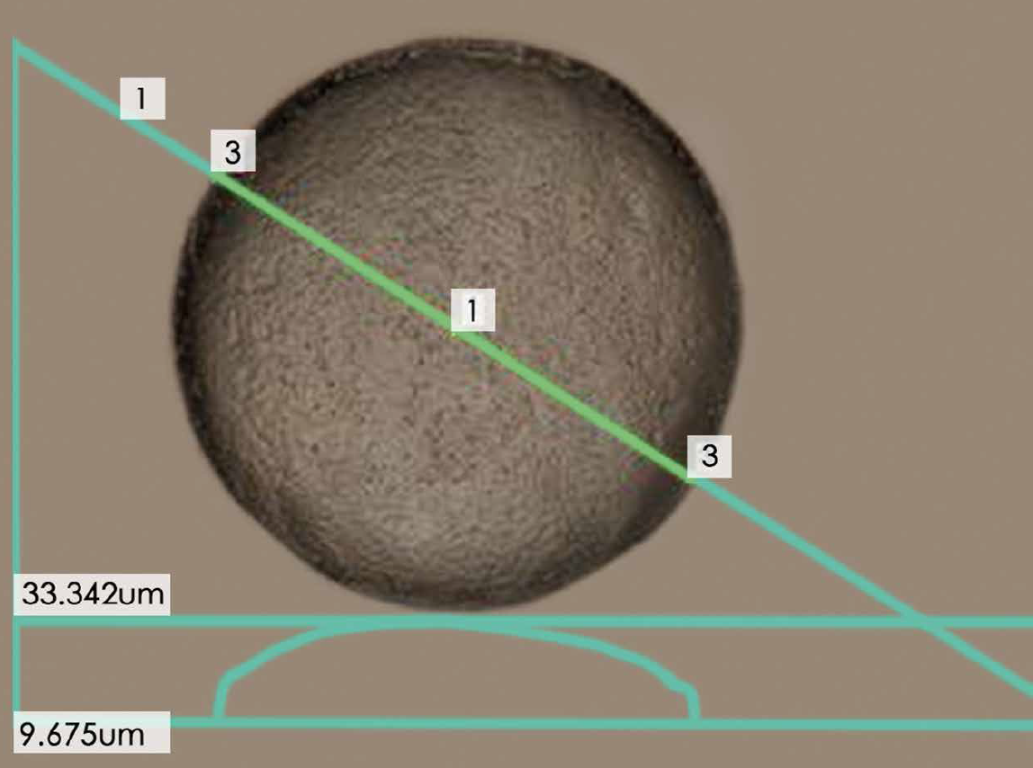
 Figure 1: Etched light extraction feature
The Hurdles
The largest hurdle to overcome in the transition, however, is that fixture manufacturers have been primarily interested in the distribution and intensity of light that is projected from the fixture into the room or space being illuminated, whereas, historically, light guide manufacturers have mainly been interested in the distribution and intensity of light at the surface of the product. This was easily addressed in linear troffer lights by utilizing standard light guide technology and adding light management films to the products. After this adoption, however, many of the requested distribution models began to include light emitting from multiple surfaces and in multiple directions from the source. Although these requests were new, they were entirely within the capabilities of light guide technology but required additional development.
A second hurdle is with regard to what optical extraction technology is used within the light guides. There are many different technologies used within the light guides, including printing and etching as secondary operations performed on plastic sheets of material, etched or machined features within a mold or tool, or etched and machined features used on thermal embossing equipment. Most of the current fixtures using light guides have utilized the higher efficiency etched and lensed designs. An example of some of these structures can be seen below.
 Figure 2: Lens-based light extraction feature
Requirement, Solution and Result
Many manufacturers have asked for a solution for use in suspended light fixtures that will allow the light to be distributed upward, for indirect illumination, as well as downward, for direct illumination. This was possible using existing light guide technology, as it had been developed for products such as flip phones with dual displays utilizing a single light guide. These light guides, however, typically produced light in a fairly indirect and relatively uncontrolled distribution. The more common request has been for a semi- Lambertian distribution in the downward direction with low glare while obtaining a bat-wing type distribution in the upward direction. This would allow for the room below the light to be evenly illuminated, while the upward light would illuminate the walls and surfaces to the sides of the fixture, creating an indirect illumination. This has now been accomplished by designing the individual light extraction features used within the light guide in order to control light in multiple directions. By changing the angle of these features, light can be directed substantially in the direction and area requested by the fixture manufacturer. In order to achieve a separate distribution in the upward and downward direction, different structures and extraction features can be used on each surface of the light guide. One such distribution is shown in figure 3.
 Figure 3: Light distribution diagram showing a separate distribution in the upward and downward direction
However, if the fixture manufacturer is interested in a slightly different profile, such as changing the angle of the light contained within the upward distribution, it can be achieved by varying the angle of the extraction features if the customer is using the machined features discussed earlier. Although the included angle of the optical extraction features is typically in the 40° range for LCD backlighting, by varying this angle of the lens relative to the surface of the light guide from 40° to 50°, or even 60°, the angle of the light being emitted from the light guide can be customized. The graphs in figures 4 a-c represent distribution plots of the light emission angle using a 60°, 50° degree, and 40° included angle for the optical extraction features.
 Figures 4 a-c: Plot of 60, 50, 40 degree upward distribution achieved by varying the angle of the extraction features
As you can see by reviewing the plots, as the included angle of the extraction feature decreases, the distribution of light becomes less parallel with the light guide and closer to perpendicular downlighting. There is a limit to this, however, and, in some instances, it is necessary to add secondary optics and films to achieve specific distributions. If the angle of the extraction feature becomes too great, the light contained within the light guide is reflected instead of being refracted and is not emitted from the surface of the light guide. For this reason most light guides utilize lenses between 40° and 60°.
The already described refraction of light, caused by the index of refraction of the material, results in some of the light rays being emitted out of the side of the opposite of the normal direction of emission. As the included angle of the light extraction feature is changed, the light that interacts with the features will be refracted out of the bottom of the light guide instead of reflecting toward the top surface and can then be utilized as usable light although in the direction opposite the primary distribution. In many products, the design will include a reflective film used to direct this light back upward in the direction of the intended distribution. This recycled light returning through the light guide after interaction with the reflective film will, in many cases, be a semi-Lambertian distribution if utilizing a white reflective film. This light will have an effect on the total distribution plot of the light emission. However, in most cases it will be a minor element. There is another opportunity to utilize this light, though.
 Figures 5 a-c: Three examples of the achievable up/ down distribution
An additional effect of the extraction features, caused by the index of refraction of the material, is the refraction of some light out of the side of the light guide containing the features. As the included angle of the light extraction feature is changed, some of the light that interacts with the features will be refracted out of the bottom of the light guide instead of reflecting toward the top surface. This light is then emitted out of the panel as usable light. In many products, the design will include a reflective film used to direct this light back upward in the direction of the intended distribution. There is another opportunity to utilize this light, however. Through manipulation of the extraction features, the light guide, without the reflective film, can be used to achieve the distinct up/down distributions that are shown in the images below.
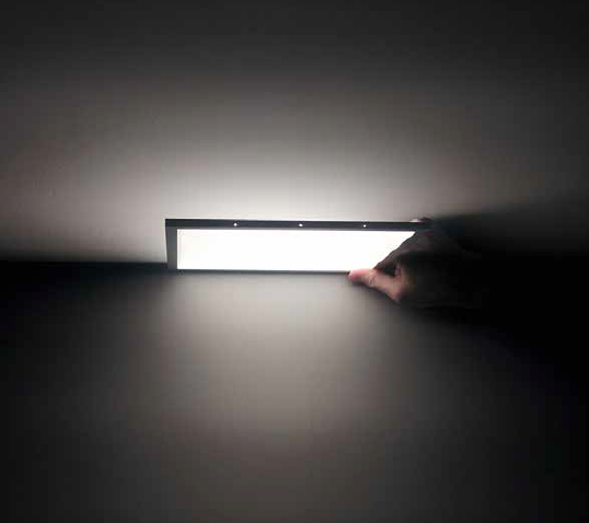
This method for utilizing edge-illuminated LED light guides now allows fixture manufacturers to achieve unique upward and downward distribution without having to direct individual banks of LEDs in each direction. The distributions available by combining the various optical features described earlier can vary greatly and can meet numerous requests from fixture designers with small variations in design. This technology is currently enabling very thin and even translucent light guide bi-directional fixtures that are now being introduced to the market.
 Figure 6: Practical application example of the demonstrated technology
Conclusions
The number of possible uses for this technology continues to grow as designers are exposed to, and educated on the possibilities. The optical design, mechanical design, and production of these products remains very specialized, with only a small number of companies capable of providing these specialized products. When implemented properly, however, the result in very impressive usage of new LED lighting technology.

