Measurement of LEDs
Various new types of light emitting diodes (LEDs) are being developed and introduced for general illumination and other applications, and there are increasing needs for accurate measurements of various optical parameters of LEDs. Traditional standard lamps do not meet the calibration needs for LED measurements as LEDs differ substantially from traditional lamps in terms of physical sizes, flux levels, spectra, and spatial intensity distributions.


 and the picture of the sphere with an LED holder (below).")
Introduction
Various new types of light emitting diodes (LEDs) are being developed and introduced for general illumination and other applications, and there are increasing needs for accurate measurements of various optical parameters of LEDs. Traditional standard lamps do not meet the calibration needs for LED measurements as LEDs differ substantially from traditional lamps in terms of physical sizes, flux levels, spectra, and spatial intensity distributions. The temperature-dependent characteristics and great variability of optical designs of LEDs make it even more difficult to reproduce measurements. To assure high accuracy LED measurements, reference standard LEDs and calibration services have been in high demand [1]. The National Institute of Standards and Technology (NIST) has recently developed and expanded capabilities for calibrating LEDs for photometric, radiometric, and colorimetric quantities and provides various calibration services for LEDs. This article discusses measurement of luminous Intensity, total luminous flux, total spectral radiant flux, and color quantities of LEDs, as well as NIST measurement facilities and calibration services for LEDs.
Luminous Intensity
The luminous intensity (unit: candela) of LEDs can be measured with a conventional photometric bench and the standard photometers [2] under a far field condition, at a distance far enough so that the test LED can be regarded as a point source (typically 2 m or longer). However, a common practice in the LED industry has been to measure LEDs at much shorter distances, such as 10 cm to 50 cm. The tradition presumably came from the time when LEDs were very dim and photometers were not very sensitive. This practice still prevails even though LEDs are much brighter. Measuring luminous intensity of LEDs at short distances is problematic because many LEDs have epoxy lenses, and they do not behave as a point source and the inverse-square law does not hold well. The effective center of LED emission can shift from the physical center of the LED. This causes variations in measured luminous intensity when measured at different distances, especially when the distance is short. This was determined to be one of major causes of variation in luminous intensity measurement.
To address this problem, the Commission Internationale de l’Eclairage (CIE) standardized the measurement distances (100 mm and 316 mm) for LED intensity measurements as published originally in CIE 127 (1997) and in recent revision CIE 127:2007 [3]. This publication also standardized the photometer aperture to be circular with an area of 1 cm2, the distance is to be measured from the tip of the LED encapsulation, and the direction of measurement is to coincide with the mechanical axis of the LED. This CIE geometry is shown in Figure 1.
The luminous intensity measured under these standardized conditions is called the CIE Averaged LED Intensity, since the value can be slightly different from the real (far-field) luminous intensity of the LED. The two distances are distinguished by Condition A and Condition B, for 316 mm and 100mm, respectively. This CIE recommendation should be used for intensity specification of individual LEDs. This recommendation does not apply for LED clusters, arrays, and fixtures made with LEDs. Test LEDs are measured against calibrated standard LEDs or a calibrated standard photometer head, with spectral mismatch correction applied as necessary.
NIST has developed standard photometers in compliance with this CIE recommendation, and has established a calibration service for Averaged LED Luminous Intensity in Conditions A and B. The uncertainty (expanded uncertainty, k=2) for these calibrations is typically 1 % to 3 % depending on test LEDs. See references [4-7] for details.
Total luminous flux
The total luminous flux (unit: lumen) is probably the most important quantity for LEDs used for illumination applications. The luminous efficacy, lumens per watt, is critical for white LEDs being developed. Compared with measurements of traditional incandescent lamps, the uncertainties of LED measurements tend to be much larger, primarily due to narrowband spectral distributions and varieties of beam pattern of LEDs. Total luminous flux of LEDs can be measured either with an integrating sphere system or a goniophotometer. When using integrating spheres, it has been common practice in the LED industry to mount LEDs on the sphere wall. This method is inappropriate in many cases, as the backward emission of the test LED is excluded and total luminous flux is not measured correctly. In the new recommendation CIE 127:2007 [3], the integrating sphere geometries as shown in Figure 2 are recommended. In cases where only forward flux is important, partial LED flux is defined also in the new CIE publication.
Geometry (a) in Figure 2 is recommended for all types of LEDs including those having a narrow beam profile or those having broad and backward emissions. This geometry should be used for most of the 5 mm epoxy type LEDs, which have backward emissions. Geometry (b) is acceptable for LEDs having no backward emission. For example, a high-power LED having a large heat sink and no backward emission can be measured with geometry (b) where only the LED head is inserted into the sphere and the large heat sink stays outside the sphere. Integrating spheres with either geometry should be calibrated with a total luminous flux standard LED having a similar angular intensity distribution and spectral distribution as the test LEDs to be measured, with spectral mismatch corrections applied as necessary. Integrating spheres with size from 20 cm to 50 cm are commonly used for LEDs.
Total luminous flux of LEDs are calibrated at NIST using the 2.5 m integrating sphere system, which is also used for the realization of the lumen and calibration of traditional lamps. Even with the very large size of the sphere, the sphere system has sufficient sensitivity for LED luminous flux measurement. The 2.5 m sphere system uses the Absolute Sphere Method as shown in Figure 3. The spectral throughput of the NIST sphere has been precisely determined and spectral mismatch correction is applied. The errors due to spatial nonuniformity of the sphere responsivity, associated with differences in LED angular intensity distributions, have also been analyzed for correction or uncertainty determination. The uncertainty (expanded uncertainty, k=2) for LED luminous flux calibration at NIST is typically 0.7 % for white LEDs and 1 % to 3 % for single color LEDs. The details of the NIST 2.5 m sphere [8] and the LED calibration procedures for luminous flux are available in references [4,9]. Geometry (a) is recommended for all types of LEDs including those having a narrow beam profile or those having broad and backward emissions. This geometry should be used for most of the 5 mm epoxy type LEDs, which have backward emissions. Geometry (b) is acceptable for LEDs having no backward emission. For example, a high-power LED having a large heat sink and no backward emission, can be measured with geometry (b) where only the LED head is inserted into the sphere and the large heat sink stays outside the sphere. Integrating spheres with either geometry should be calibrated with a total luminous flux standard LED having a similar angular intensity distribution and spectral distribution as the test LEDs to be measured, with spectral mismatch corrections applied as necessary. Integrating spheres with size from 20 cm to 50 cm are commonly used for LEDs.
Total luminous flux of LEDs are calibrated at NIST using the 2.5 m integrating sphere system, which is also used for the realization of the lumen and calibration of traditional lamps. Even with the very large size of the sphere, the sphere system has sufficient sensitivity for LED luminous flux measurement. The 2.5 m sphere system uses the Absolute Sphere Method as shown in Figure 3. The spectral throughput of the NIST sphere has been precisely determined and spectral mismatch correction is applied. The errors due to spatial nonuniformity of the sphere responsivity, associated with differences in LED angular intensity distributions, have also been analyzed for correction or uncertainty determination. The uncertainty (expanded uncertainty, k=2) for LED luminous flux calibration at NIST is typically 0.7 % for white LEDs and 1 % to 3 % for single color LEDs. The details of the NIST 2.5 m sphere [8] and the LED calibration procedures for luminous flux are available in references [4,9].
Total Spectral Radiant Flux
Integrating spheres equipped with a spectroradiometer as the detector of the sphere as shown in Figure 4 (see LpR magazine), called sphere-spectroradiometers, are increasingly used for measurement of LEDs. This is a convenient way of measuring photometric quantities and color quantities at the same time. This type of instrument measures total spectral radiant flux (unit: W/nm), from which total luminous flux, total radiant flux, and color quantities (spatially integrated) are obtained. Another advantage is that total luminous flux can be measured theoretically with no spectral mismatch error. By using an array spectroradiometer, the measurement can be as fast as a sphere-photometer system. Such sphere-spectroradiometer systems need to be calibrated against a total spectral radiant flux standard.
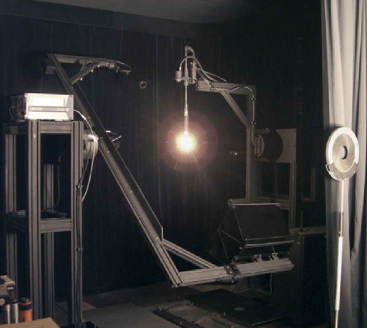
NIST has recently established a total spectral radiant flux scale for the 360 nm to 830 nm region, using a gonio-spectroradiometer system as shown in Figure 5, and offers calibration services [10]. The scale is disseminated by issuing calibrated total spectral radiant flux standard lamps (75 W quartz halogen lamps) and by providing calibration of lamps submitted by customers.
See Figure 5 (see LpR magazine)
Total Radiant Flux
Total radiant flux (unit: watt) is a spectrally and spatially integrated total radiant flux of a source. Radiant power and optical power are also often used for the same meaning for LEDs. This quantity is necessary to specify LEDs in the UV and IR regions, and is also useful for single color LEDs, as the values of lumen change dramatically depending on the peak wavelength even within the same color range making it difficult to compare the lumen values. For LEDs in the visible region, the total radiant flux can be converted from the luminous flux value and LED’s relative spectral distribution. However, the uncertainty increases, especially at near the wings of the V( ) function. NIST provides calibration services for total radiant flux of LEDs in the 360 nm to 830 nm region using the NIST 2.5 m absolute sphere system configured for a total spectral radiant flux mode, as shown in Figure 6. The calibration is based on the NIST spectral irradiance scale. The spectroradiometer is a CCD-array type and is corrected for spectral stray light [11]. For the details for total radiant flux calibration, see reference [12].
See Figure 6 (see LpR magazine)
Color Quantities
Color quantities such as chromaticity coordinates, dominant wavelength, correlated color temperature (for white LEDs), and Color Rendering Index (for white LEDs), are used to specify color characteristics of LEDs. Even if a spectroradiometer calibrated traceable to national standards is used, the uncertainty in measured color of LEDs is often unknown or unexpectedly large, and thus reference LEDs calibrated by national laboratories are often needed by users to verify the accuracy of LED color measurements.
See Figure 7 (see LpR magazine)
NIST has developed a reference spectroradiometer for LED color measurement (CIE Condition B geometry), using a double-grating monochromator with irradiance input optics. This spectroradiometer is tuned to have a triangular bandpass of 2.5 nm width (FWHM) and scans at 2.5 nm intervals. The uncertainties in LED calibrations for any color are within 0.001 in CIE (u’, v’) chromaticity. Figure 7 shows the optical design of the NIST spectroradiometer system. Further details on the reference spectroradiometer can be found in reference [13].
In addition to directional color calibration, spatially-averaged color quantities of LEDs integrated over the entire emission angles are available from the total spectral radiant flux measurement as described above. It is recommended that white LEDs be measured for spatially averaged values, as the color tends to shift with viewing angle. The spatially-averaged color quantities are measured at NIST using the facility described above for total radiant flux. Calibrations of either directional or spatially-averaged color quantities of LEDs are available from NIST.
Strategy on standard LEDs in NIST calibration services
Some NIST calibration services issue calibrated artifacts and others calibrate artifacts submitted by customers. We decided not to prepare and issue “standard LEDs” because there are so many types of LEDs and new types of LEDs are continuously being introduced, and thus, any standard LED we might develop would not satisfy many customers and would quickly become obsolete. We are committed to providing calibrations for any type of LEDs submitted by our customers, which can then be used as reference standard LEDs of the type needed in the customer’s lab. Customers are responsible to ensure the quality of LEDs submitted to NIST for calibration. Information on the NIST photometric calibration services is available on the website [14] or by contacting the authors.
