Natural Design for Heat Sinks
The luminous flux of LEDs decreases with the rise of the operating temperature. Therefore the dissipation of the heat is, aside from the efficiency of the LED chip itself, an essential part in the development of efficient LED systems. Christian Herbold and Cornelius Neumann from the Light Technology Institute at the Karlsruhe Institute of Technology analyzed natural inspired shapes and show an approach to heat sinks that combine high thermal performance with a high aesthetic value.
The luminous flux of LEDs decreases with the rise of the operating temperature. Therefore the dissipation of the heat is, aside from the efficiency of the LED chip itself, an essential part in the development of efficient LED systems. The request for smaller LED luminaires with higher light output makes it more and more important to care about a potent heat management. Unfortunately powerful heat sinks are often in conflict with the desired product design of the luminaire. To avoid this, they are frequently covered or modified, which results in an advanced appearance but leads to a reduction of the thermal performance. Could it be possible to solve this problem with a look at nature?
The analysis of natural inspired shapes will show an approach to heat sinks that combine high thermal performance with high aesthetic value. Based on mathematical models and computational fluid dynamic analysis, a branched architecture was improved to obtain high performance heat dissipation. In addition, the resulting geometry shows a natural aesthetics that can serve as the origin for the design of efficient and beautiful luminaires. The modeled heat sinks are manufactured with metal injection molding to evaluate the process for the construction of such parts.
Basic Problem
Most properties of an LED depend on the temperature. Not only the luminous flux and therefore the efficiency but also the lifetime, wavelength and the chromaticity coordinates change with temperature. The higher the temperature, the more the properties are influenced negatively. In general, there are three physical mechanisms to transport heat: radiation, conduction and convection. The design of a heat sink has to consider these mechanisms to improve the thermal performance.
In comparison to traditional incandescent lamps the thermal power loss of the LED itself is not radiated and has to be dissipated by thermal conduction from the LED into the applied heat sink. The design of the heat sink has to ensure that the heat is conducted through the material to the surfaces where it is transported to the environment by convection and radiation. Considering a given space available for a heat sink and thus the same surface area of circumference, the special design of the heat sink has a minor impact on the heat dissipation by radiation whereas the heat conduction and convection are effected by the material and the geometry of the heat sink. Thus, the design of a heat sink has to fulfil two aims: good thermal conduction in the heat sink and good thermal convection on its surfaces.
Basic Idea
A look at nature could possibly help to find architectures that support this solution. Evolution formed methods optimized for specific tasks that are efficient when it comes to the use of energy and material. This efficiency is advantageous to survival when there is limited availability of plant nutrients, space or light. The requirements of a living organism differ from the utility function in technology and therefore the approaches taken from nature cannot be copied for their technical use. Naturally inspired principles in technology must therefore be abstracted from their natural model to serve as innovative and powerful solutions.
When comparing the tasks of organisms absorbing and distributing energy in the form of nutrients with the task of the heat sink transporting and dissipating energy in the form of heat, the similarity is obvious. The results of the evolutionary process are efficient solutions for these tasks in many different structures. For example; the branched system of the human blood circulation or the venation of leaves. The architecture of tree branches or tree roots are both shaped efficiently in order to take in and transport plant nutrients while saving material and conserving the structural stability. Although the specific design varies even within the same species influenced by environmental effects, the basic principle of the branched architecture is always the same. For millions of years evolution formed these efficient shapes that everybody knows from every day life. This has always made nature a source of inspiration when it comes to the design of the human environment. Many successful designs were built on natural models with shapes and processes that build a harmonic balance with the environment [1]. Therefore heat sinks for LED systems could benefit in two ways from a natural inspired design. They may take advantage of a natural architecture in regards to the technical function of dissipating heat and, in addition, they connect the intrinsic beauty of nature with the design of the luminaire.
Technical Investigation
Determining technical performance of branched heat sinks for LED systems is done in several steps. After applying a mathematical approximation to analyze the basic factors, CFD (computational fluid dynamics) simulations are performed to get detailed knowledge of the processes in the heat sink. In a final step a reference heat sink is produced to provide real world measurements and a comparison to the predictions of the simulation. To follow the constraints of most LED applications in general lighting, only the free air convection without supporting fans is examined. In addition all heat sinks considered are based on a round footprint. This shape supports the natural example, follows the circular spreading of heat from the source and orientates on the common design of luminaires that are mostly built rotation-symmetrically. With regard to the latest high power LEDs that offer more than 1,000 lm out of one package, the heat sink is designed for a system with a single LED of several Watts electrical power.
The characteristic number to describe the ability to dissipate heat in general is the thermal resistance Rth with the unit K/W that expresses the rise in temperature per thermal power put into the system. The better the heat is dissipated, the smaller the thermal resistance of the component is. A mathematical approach was used to estimate the thermal resistance of naturally branched structures. It is based to the assumption of the steady state and considers the energy loss in the branch by heat conduction and heat convection. The bifurcations are modeled by a recursive rule to calculate the thermal resistance of the whole branch. Input parameters are geometric properties of every single sector of the branch including its length, width and height, the thermal conductivity of the material and the heat transfer coefficient on the surfaces. This coefficient takes account of the geometry of the heat sink because it respects the flow conditions round the surfaces that are influenced by the space available for air flow. Details of this approach are described in [2].
The mathematical approximation is compared to more accurate but also more complex thermal simulations of the same branch. Based on numerical fluid mechanics, the simulations are performed for a high resolution mesh of discrete volumes of the branch model. To achieve precise results the small structures in the branches are considered by refining the mesh in the corresponding areas. The results compared to the approximated calculation are shown in figure 1 for a branch with different numbers of bifurcations but the same total length. Although there is a difference in the absolute values, the trend of both curves is similar. With an increasing number of bifurcations, thermal resistance initially decreases. After reaching its minimum value it increases again. This effect is caused by a change in convective heat dissipation with the length of the branched sectors. Considering a constant total length and material volume of the branch the surface for convection is increased with every new bifurcation. At the same time each new sector reduces the space between the neighbor branches and affects the airflow between the surfaces negatively. At a specific number of bifurcations the reduced airflow no longer compensates the benefit from the newly generated surfaces. In consequence the thermal resistance rises. If the spacing between the surfaces is too small, the fluid-flow through the channels is hindered and the heat transport by convection is reduced. and simulation results of the same branch (black)") Figure 1: Approximately calculated trend of thermal resistance for one branch (grey) and simulation results of the same branch (black)
Figure 1: Approximately calculated trend of thermal resistance for one branch (grey) and simulation results of the same branch (black)
Branched Design
Based on the results of the mathematical approximation, different parameters of the geometry are evaluated in detail by thermal simulations. The design of the simulated heat sinks is based on the branched architecture and meets the requirements of a small luminaire based on a single high power LED. The branches are constructed in one plane that is extended in the third dimension to form a cylindrical body. To ensure the comparability of the different designs, this cylinder has a diameter of 50 mm and a height of 50 mm in every design. All simulations are performed with a thermal power dissipation of 7 W on an area of 5 mm x 5 mm in the middle of the bottom end plane. This power dissipation corresponds to at least 10 W electrical power input at the LED.
The heat sink design for the available space is determined on the basis of the mathematical model in conjunction with several thermal simulations and approximated with the numbers of branches, bifurcations and the bifurcation angle. The number of bifurcations corresponds to the value of three. The width of the branches is thereby specified not only to allow a sufficient thermal conduction but also for mechanical stability reasons and the ability of the manufacturing process. A minimum width of 1 mm complies with these requirements. With every bifurcation the width of the branch is divided in half. On the one hand this maintains the cross section constant for the thermal conduction, on the other hand it assures the stability needed during the production of the part. The minimum given thus defines the width of the previous sectors to 2 mm and 4 mm, respectively. All these specifications describe the major geometry of the heat sink but leave space for details that have to be examined. One example is the number of branches that directly influence the spacing between the surfaces. The heat sinks in figure 2 contain five to nine branches with two bifurcations in every branch. The simulation results in Table 1 show that the lowest thermal resistance of these designs is achieved with seven branches where the difference is up to 12%. The low number of branches in heat sinks 1 and 2 wastes space for additional surfaces while the large surfaces of heat sinks 4 and 5 cause narrow flow channels between the branches. This effect corresponds directly to the optimal spacing that is described for parallel plates in [3] and approximated for a more practical use in [4].
 Figure 2: Top view of heat sink simulation models with different number of branches
 Table 1: Simulation results for different numbers of branches
Comparison
The performance of the branched heat sink is compared to the thermal resistance of a non-branched heat sink to validate the predictions of a lower thermal resistance with a branched architecture. The non-branched heat sink is designed to match the geometrical parameters of the branched heat sink. With the same constructed size (diameter and height) and the same diameter of the core, the material volume and the surface area differ with less than 1%. This leads to a conventional design with 17 fins. The difference between branched and non-branched design is expected to rise with the diameter of the heat sink because of the higher difference in spacing for larger diameters. Although the given diameter of 50 mm is relatively small to demonstrate the advantages of the branched design, the results of the thermal simulations confirm the expectations. Figure 3 shows the temperature distribution on the surface of both types as well as the flow velocity in the center plane. The higher temperatures and the areas with low flow velocity at the branched heat sink are obvious. The thermal resistance of the non-branched heat sink is 8.3% higher compared to the thermal resistance resulting for the branched version. With the manufacturing of both heat sinks it will be evaluated if this advantage can be transferred in a real heat sink.
 Figure 3: CFD simulation results for temperature and flow velocity for branched and non-branched heat-sinks
Manufacturing of Prototypes
The heat sinks are manufactured as samples considering a large scale manufacturing process. The injection molding offers the combination of high quantity parts with a high level of design freedom. The typical application for injection molding is the production of plastics parts. However, with the option of powder injection molding the same process can be extended to metals and ceramics from which copper was chosen for the first sample parts due to its high thermal conductivity compared to other metals.
For the injection molding process copper powder is mixed with a polymer as binder and granulated to compose the feedstock. The feedstock is melted and molded on a conventional injection molding machine Arburg Allrounder 570 S. The resulting green part has the final shape but not the final size because it still consists of copper powder and the binder material. The water soluble part of the binder can be removed of the part in a water bath. It still remains the so-called backbone that slightly connects the powder particles and keeps the part in its shape. A drying process follows because it is necessary that no water is present during the next step. This step consists of the thermal de-binding to remove the backbone and the sintering to produce a dense part out of the powder.
Metal injection molding (MIM) is mostly used for small parts with typical weights between 1 g and 100 g [5].
Parts like the constructed heat sinks with about 330 g raise two problems for the injection molding of metals. The size makes it difficult to fill the whole cavity with melt before it solidifies. Once filled, the large surface causing a large surface adhesion prevents an easy ejection of the molded part. The cylindrical shape of the sample heat sinks offers two advantages to deal with these problems. Due to the extruded geometry the whole cross-section area can be used as ejector. For this reason, the pressure to push the molded part out of the cavity is applied to the complete cross-section area and the risk of destroying the part during ejection is reduced. Furthermore, with this construction the ejector can be used for compression molding to support the filling of the cavity. During the injection the volume of the cavity is enlarged with back-pressure against the injected melt. Thereby the melt completely fills the available volume. These two additional functions of the ejector support the manufacturing of reasonable parts but small defects still remain on the final samples. It is not possible to eject a completely filled heat sink with high contour accuracy without destroying it. Due to the surface adhesion the fins break on the bond to the core of the heat sink. By slightly reducing the filling degree the parts can be ejected without breaks but the molded heat sinks have some notches on the fins where the cavity was not completely filled.
The following de-binding and sintering process finish the parts. During the sintering the heat sinks shrink evenly to about 85% of the size of the green part. A shape distortion caused by the shrinkage can almost be avoided with an appropriate sintering support that minimizes friction between the parts and the base. Figure 4 shows the sintered heat sinks of both types. The shapes represent the constructed geometries very well. The notches caused by the necessary reduced filling degree can be seen at half height of the parts. The difference in weight is slightly higher than expected. The branched heat sink is 6% lighter than the non-branched type.
 Figure 4: Metal injection molded copper heat sinks after sintering
First Measurements
For the thermal analysis of the heat sinks the thermal transient testing method is used because of its accuracy and the ability to characterize the heat sinks in the system they are designed for. When measuring the thermal behavior of LED systems a combined thermal and radiometric measurement setup has to be used since the supplied energy is dissipated in the form of light and heat. To avoid the need for a combined measurement and the related uncertainties, a diode is applied to the heat sinks. This diode features the thermal dissipation of all electrical power that is brought into the system with a similar footprint to the LED. First measurements support the predication from the simulations although the measurements have not yet been performed with the power the heat sinks were constructed for. Therefore the difference of 5.2% between both designs is lower but observable. In the next step the heat sinks will be characterized for full heat dissipation. Optical measurements with LEDs will supplement the results and a comparison to standard heat sinks will be possible.
Conclusions and Outlook
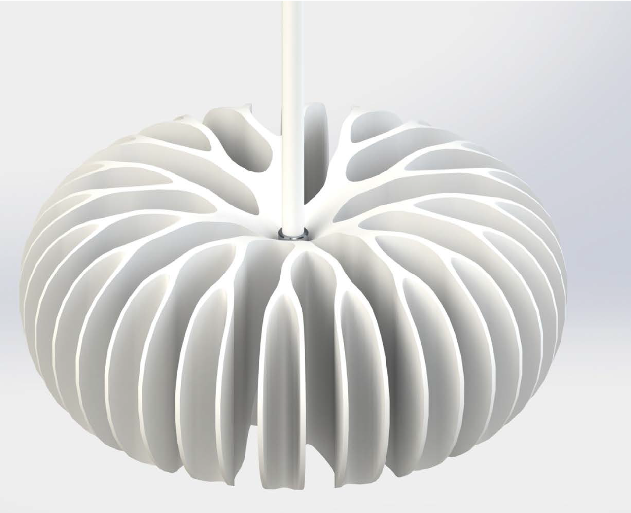
Inspired by natural architecture, branched structures were analyzed concerning their ability to serve as heat sinks in LED applications. Based on an approximate mathematical model and several thermal simulations a branched heat sink was designed. A corresponding heat sink in a conventional non-branched design serves as reference. The comparison to thermal simulations results in an advantage of 8.4% for the branched heat sink in the given size. Both designs were manufactured from copper with metal injection molding. First measurements confirm a slightly lower thermal resistance of the branched heat sink. Although the advantage in performance is small in these models, the advantage in the design is still evident (Figure 4) even if the design freedom given by the manufacturing process of MIM is not extensively used. Compared to a luminaire with covered heat sink, an increased difference in performance will be obvious. Therefore an additional design will be manufactured to combine the natural shapes with the possibilities of the process. Heat sinks with larger diameters will extend the advance in thermal resistance. The beauty of the branched architecture is certainly worth thinking about luminaires designed on this principle, joining aesthetics and performance (Figure 5).
 Figure 5: Possible heat sink design based on branched architecture
References:
[1] A. Sachs, B. Bergdoll, D. Gamboni and P. Ursprung: Nature Design. Museum für Gestaltung Zürich, Lars Müller
Publishers, Zürich 2007
[2] C. Herbold and C. Neumann: Vorbild Natur: Bionische Strukturen zur Entwärmung von LEDs. Tagungsband LICHT,
Berlin 2012
[3] A. Bar-Cohen and W.M. Rohsenow: Thermally Optimum Spacing of Vertical, Natural Convection Cooled, Parallel Plates.
J. Heat Transfer, 106, pp. 116-123, 1984
[4] A. Bejan and S. Lorente: Design with Construcal Theory. John Wiley & Sons, Inc., Hoboken, New Jersey 2008
[5] MIM-Expert-Group and Fraunhofer-IFAM: Metal Injection Moulding (MIM), Powder Injection Moulding, 2012
