Optical Designs to Improve LED Lighting Efficiency of Medical Endoscopes
Lighting efficiency for endoscopic instruments has been deemed very poor, at only about 20%. While laboratory tests demonstrate that fiber optics bending is not problematic, optical simulations clearly show that lighting efficiency is strongly limited by the Étendue. Because of strong geometrical constraints in the light coupling area of an endoscope system, only a radical new optical design can provide significant improvement. Alexander Gaertner and Paola Belloni from the Faculty of Mechanical and Medical Engineering and the Steinbeis Transferzentrum Lichttechnik und Beleuchtungsoptik at the University Furtwangen discuss these issues and propose possible approaches.
The presented work focuses on the improvement of the degree of efficiency of the illumination optics of rigid medical endoscopes to provide more light in the surgeon’s field of view and therefore better image quality. At first, the photometric and colorimetric properties of typical external LED light sources that power state-ofthe- art endoscope systems were measured. Further measurements of the efficiency of the whole endoscope systems surprisingly showed very low values of about 16%- 19%. Both the endoscope´s geometrical components as well as the critical optical interfaces have been implemented in a 3D-optomechanical-simulation model. By means of optical simulations we developed alternative optical components inside the endoscope to optimize light collimation to the target surface. The optimization takes into account both spectral and angular light distribution of the external LED light source as well as material absorption caused by manufacturing processes.
The investigations showed that because of the physical constraints given by the Étendue, a significant improvement of the efficiency of typical rigid endoscopes can only be achieved by radically changing the geometries and the mechanism that allow light transport and outcoupling.
Introduction
Over the past years, endoscopes have become an essential part of minimally invasive surgery and, nowadays, are indispensable in operating rooms. Especially illumination has always been a great challenge for every type of endoscope and is now more important than ever, since endoscopy systems become smaller and more complex. Each endoscope is provided with an illumination optics that guides light from an external light source to the distal end of the endoscope and an imaging optics that captures reflected light from the surgical field and guides it to the proximal end to further images processing.
We distinguish between rigid, flexible and newly developed capsule endoscopes. In capsule endoscopes, illumination is realized by integrating LEDs that directly illuminate the field of view [1]. However, integrating LEDs in rigid and flexible endoscopes present challenges with respect to heat dissipation in order to be compliant with the strict regulations regarding temperatures and electrical safety of medical equipment as defined in the European normative DIN EN 60601 [2]. Recently KARL STORZ introduced a Uretero-Renoscope with LEDs integrated in the handle [3]. But up to now, an integrated LED-illumination is not state of the art yet and the actual light source is placed outside the endoscope in an external unit.
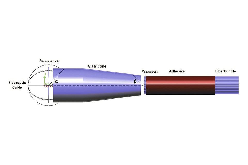
Figure 1 describes in a schematic way the illumination optics components integrated into a rigid endoscope. An external light source is connected to the endoscope via a fiber optic cable with a typical diameter in mm range. From there, the illumination optics typically consists of two components: a small cone-shaped optics and a fiber bundle in which single glass fibers are embedded into an adhesive. Light is coupled from AFiberopticCable under an angle α into the glass-condensing cone and is coupled out under a range of angles that depends on the collimation properties achieved. But only rays that hit the surface AFiberbundle inside the acceptance angle β of the glass fibers are transferred to the distal end of the endoscope to finally illuminate the field of view of the surgeon.
 Figure 1: The typical illumination optics of a rigid endoscope: a fiber optic cable, a coneshaped optics and a fiber bundle in which single glass fibers are embedded into a light absorbing adhesive. The dimension of a single fiber optics is in μ-range, the fiber bundle has a diameter of a few mm
Analysis of LED-Light Sources and Endoscopes
The first step of our optimization approach is the photometric and colorimetric analysis of external LED-Light sources. The results obtained are thus implemented in the optomechanical simulation model developed with LightTools (Synopsys©) and further considered in the optimization procedure.
Therefore, at first the illuminance values of state-of-the-art external LED-light sources in the lighting technology laboratory was measured. All fiber optic cable measurements were carried out with an integrating Ulbricht sphere (D=25 cm; Instruments systems) and a goniophotometer with integrated spectrometer for angular dependent spectral measurements (Czibula and Grundmann).
 Spectrum 1 shows a typical phosphorconverted white LED with a CCT=5600 K whereas Spectrum 2 is an RGB system. Angular distribution curve of the light output, showing a maximum aperture/ cut off angle of ±36°. (b) The graphs show the angular dependent spectral properties of Spectrum 1") Figures 2a&b: Examples of the LED-light sources properties measured at the fiber cable end. (a) Spectrum 1 shows a typical phosphorconverted white LED with a CCT=5600 K whereas Spectrum 2 is an RGB system. Angular distribution curve of the light output, showing a maximum aperture/ cut off angle of ±36°. (b) The graphs show the angular dependent spectral properties of Spectrum 1
Figures 2a&b: Examples of the LED-light sources properties measured at the fiber cable end. (a) Spectrum 1 shows a typical phosphorconverted white LED with a CCT=5600 K whereas Spectrum 2 is an RGB system. Angular distribution curve of the light output, showing a maximum aperture/ cut off angle of ±36°. (b) The graphs show the angular dependent spectral properties of Spectrum 1
All measurements are performed according to DIN EN 13032-4 [4]. Most of the LED-light sources show the typical phosphor-converted white light spectrum with a CCT between 4600 K and 6100 K and the expected angular dependence of spectral properties. But quite surprisingly one spectrum is an RGB system. All angular distribution curves measured at the fiber optic cable end are rotationally symmetric and show a cut-off angle. This is an important parameter for optimizing the illumination optics in the optomechanical simulation model.
Thus, the external LED-light sources were connected to three different endoscopes of leading OEMs in the medical sector and measured the illuminance values. The external light sources are typically adjustable to different brightness levels in order to better suit the specific needs of the surgeon.
The following three brightness levels were analyzed:
• Level 1 (minimum)
• Level 5 (mean) and
• Level 10 (maximum)
Each measurement was repeated 10 times and over a period of 1 hour with measurement intervals of 5 minutes.
 to three endoscopes of leading OEMs (blue bars). Measurements are performed at different intensity levels") Figure 3: Illuminance losses that occur when connecting one representative external LED-light source (green bars) to three endoscopes of leading OEMs (blue bars). Measurements are performed at different intensity levels
Figure 3: Illuminance losses that occur when connecting one representative external LED-light source (green bars) to three endoscopes of leading OEMs (blue bars). Measurements are performed at different intensity levels
Figure 3 clearly demonstrates that very high illuminance losses occur when the external light source is connected to the endoscope systems. Indeed, all the endoscope systems examined in this study reveal a total degree of efficiency of only 16%-19%. The degree of efficiency of an endoscope is defined here as a ratio between luminous flux out of the endoscope relative to that of the fiber optics one.
Moreover, it has to be considered that this result is not specific for the external light source shown in figure 3. In fact, an analysis of other standard light sources on the market delivered the same results when connected to the endoscopes [5]. This allows the conclusion that some bottleneck effects among the components of the endoscope systems must be at the origin of such lower efficiency.
Modeling the Endoscope System
In LightTools (Synopsys©) the optomechanical model of one of the endoscope systems previously measured was built and the spectral properties and angular light distribution of the LED light source were implemented. Fiber bundles in rigid endoscopes are typically glued. Adhesive fills intermediate gaps between single fibers and fully absorbs incident rays. In this simulation model the fiber bundle is embedded into the adhesive, which is implemented as an absorbing layer (Figure 1). However, the production of fiber bundles is not an automated process and therefore every endoscope has a different alignment of single fibers. These manufacturing constraints imply inaccuracies in the optical simulations because only defined alignment patterns (e.g. rectangular or hexagonal) can be simulated and they do not accurately correspond to the real alignment in a rigid endoscope.
The first goal was to investigate the absorption in the materials used by means of optical simulations. The analysis of the wavelengthdependent material losses shows that in the glass condensing cone bulk absorption and multiple reflections lead to marginal losses. Moreover, dispersive losses within the glass fibers of the fiber bundle were considered, which have a typical length of approximately 300 mm. If light is efficiently coupled into the glass fibers of the fiber bundle, the absorption losses in the fiber optics itself are negligible.
Therefore, the analysis focused on two critical optical interfaces that can cause high efficiency losses in rigid endoscopes:
• Light coupling between fiber optic cable of the external light source
and glass condensing cone
• Light coupling between glass condensing cone and fiber bundle
We found out that most light losses occur at the second critical interface between the glass condensing cone and fiber bundle.
Étendue Efficiency Constraint
The reasons for the high losses at this critical interface are the constraints given by the Étendue: limitations of the glass condensing cone to focus light on the target surface AFiberbundle and in a solid angle within the angle of acceptance of the glass fibers Ωβ (Figure 4).
, the optical system as a black box (glass cone) and the image on the right (Fiber bundle). Ωα is the solid angle subtended at the source by the entrance aperture of the optical system, Ωβ is the solid angle subtended at the image by the exit aperture") Figure 4: Schematic view of Étendue efficiency calculation with the source on the left (Fiber optic), the optical system as a black box (glass cone) and the image on the right (Fiber bundle). Ωα is the solid angle subtended at the source by the entrance aperture of the optical system, Ωβ is the solid angle subtended at the image by the exit aperture
Figure 4: Schematic view of Étendue efficiency calculation with the source on the left (Fiber optic), the optical system as a black box (glass cone) and the image on the right (Fiber bundle). Ωα is the solid angle subtended at the source by the entrance aperture of the optical system, Ωβ is the solid angle subtended at the image by the exit aperture
Figure 4 shows the Étendue efficiency calculation for the source, optical systems and image plane characteristic of the endoscope system described in Figure 1. The area of the source times the projected solid angle of the emission defines the limit of the Étendue (AFiberopticCable*Ωα). If the product of the aperture area of the collection optics and the projected solid angle of the output distribution (AFiberbundle*Ωβ) is less than this limit, there will be an efficiency loss quantified by their ratio [6]. In most endoscope systems AFiberbundle is significantly smaller that AFiberopticCable, while α and β are comparable, resulting in an Étendue efficiency significantly smaller than 1. Moreover, because of adhesive absorption in the intermediate regions among the single glass fibers of AFiberbundle, final efficiency will be even lower.
Optical Development
Taking into account the constraints given by Étendue optical alternatives to the glass-condensing cone were designed to maximize the system’s theoretical degree of efficiency. In fact, the glass-condensing cone focuses light on a surface much bigger than the target surface AFiberbundle. Moreover, a significant fraction of the light that reaches the fiber bundle has an angular aperture greater than Ωβ.
Some examples are shown in Figure 5. On the left side, concentrator 1 illustrates a Compound Parabolic Concentrator (CPC) developed using the standard LightTools CPC-Utility for a light source whose surface area and entrance and exit solid angle are known. On the right side, concentrator 2 demonstrates a CPC developed as a free geometry using the software’s optimization engine. In the optimization process surface area and entrance solid angle of the light source are kept constant while the optimization parameters target surface and exit solid angle are equally weighted in the merit function.
 Figure 5: Development of two concentrators to focus the light of the LED external light source on the target surface AFiberbundle and inside the solid angle Ωβ. The wireframe view shows the problems of back reflections
This optimized CPC model only obtained a marginal efficiency improvement, which, after absorption in the adhesive layer of the fiber bundle, resulted in 21%, against the 16%-19% measured values of the current endoscopes.
We also designed optical systems made up of lenses and of a combination of lenses and CPCs. However, the best result was achieved by using CPCs only.
Conclusion
The typical geometrical configuration of light sources and fiber bundles in rigid endoscope systems is the reason for the low degree of efficiency (only 16%-19%) of the illumination optics of state-of-the-art endoscopes on the market. In fact, both the target surface and the exit solid angle are very small compared to the source area and emission solid angle, which is the reason for the low Étendue efficiency.
Aware of this limitation, we optimized the optical design of the central collimation unit in a rigid endoscope and obtained a slight improvement of the efficiency by means of a CPC-system. It is clear that the improvement potential is limited by the Étendue efficiency constraint and therefore this approach turned out to be not worthy of following.
A more efficient illumination optics can only be achieved by radically changing both the geometries and the mechanisms that allow light collimation, transport and outcoupling inside the endoscope. Therefore, the future work will focus on these alternative approaches to avoid Étendue limitations.
Acknowledgements:
The authors thank the German Federal Ministry of Research and Education (BMBF) for its financial support of the project EDISON (Endoscopy
Illumination System Optimization). EDISON is one of the ten projects in the research frame work initiative CoHMed (Connected Health in
Medical Mountains) aimed at transferring current scientific trends in medical technology to biologize, miniaturize, and digitalize medical
devices with industrial partners of the University of Furtwangen
References:
[1] Shrestha R, Mohammed SK, Hasan MM, Zhang X, Wahid KA.
Automated Adaptive Brightness in Wireless Capsule Endoscopy Using
Image Segmentation and Sigmoid Function. IEEE transactions on
biomedical circuits and systems 2016; 10: 884-892.
[2] Norm DIN EN 60601-1:2006, Medizinisch elektrische Gerate - Teil 1:
Allgemeine Festlegungen fur die Sicherheit einschließlich der
wesentlichen Leistungsmerkmale-Deutsche Fassung EN 60601-1:2006;
Januar 2007
[3] KARL STORZ; Highlights 2016 - Telepräsenz Bildgebende Systeme,
Dokumentation, Beleuchtung, Gerätewagen: „Innovative
Visualisierungsmodi in 2D und 3D"; 2016.
[4] DIN EN 13032-4. Light and Lighting - Measurements and presentation
of photometric data of lamps and luminaires - Part 4: LED lamps,
modules and luminaires; German version EN 13032-4:2015.
[5] Alexander Gaertner and Paola Belloni (2018): Analysis and Simulation
of the Illumination Optics of Rigid Medical Endoscopes. In:
Current Directions in Biomedical Engineering. To be published in
September 2018.
[6] Mark E. Kaminski, "LED illumination design in volume constraint
environments", Proc. SPIE 5942, Nonimaging Optics and Efficient
Illumination Systems II, 59420F (20 August 2005)
