Reliable Thermal Management of High-Power LEDs by Haeusermann
Stefan Hörth believes that FR4 PCBs can easily replace IMS PCBs and even open new fields of LED applications. Haeusermann’s HSMtec Product Manager demonstrates that common FR4 laminates, including special copper filling, will sufficiently withstand the heat of HB LEDs.
LEDs are generally considered as reliable, stable and durable, and with good reason. This is definately true for single LEDs, but lamps are comprised of multiple LEDs in a small space together with control circuits and PCBs. The small lighting components are very susceptible to high temperatures, and the PCB has to act as a cooling element. LED reliability and PCB reliability are very closely connected and pose high demands on design and development.
While LEDs offer enormous design opportunities, their light quality is crucial for their acceptance as an illuminant in general lighting. The requirements in terms of light homogeneity and color temperature are high since even a discrepancy of a few Kelvin makes a tangible color difference to the human eye. In order to keep the brilliant light quality for a long time it takes clever control electronics as well as efficient thermal management. Even though the degrees of efficiency of LEDs are constantly getting better, there’s still a large part of the electric input power converted into heat. However, the functional temperature limit is the range within which the electrical circuits can be expected to meet their specified performance. The absolute maximum temperature limit is the temperature that a portion of the component may be safely exposed to. Figure 1: HSMtec dissipates the heat of tightly packed LED arrays quickly, preserving the luminosity for a long time – for example in LDDE’s LED stage spotlight SpectraWow+
This might pose a problem in today’s arrays with many tightly packed LEDs, and UHB components (Ultra High Brightness) with ten or more Watt per package. Most UHB LEDs offer just a small area of a few square millimeters for heat dissipation, so the heat needs to be channeled away quickly directly beneath the LED through a PCB with little thermal resistance.
Consequently, preventing a decrease in light quality of a LED takes changes in the board’s construction, optimizing heat dissipation so that the LED remains within its optimum operational parameters. In order to do this it is necessary to take into account the amount of heat that has to be dissipated, the dimensions, the components contacting and the circuit complexity. Concerning thermal management, there are some special PCB technologies around, like Insulated Metal Substrate (IMS) based on aluminum or Metal Core Printed Circuit Boards (MCPCB).
There are different types of MCPCBs available. A MCPCB consists of a number of layers including a dielectric sandwiched between two metal layers. One of the metal layers, typically a copper foil between 35μm and 1.5mm thickness, acts as a circuit layer for electrical connections, while the other serves as a heat spreader. Most of them are made of aluminum or copper alloy, but iron alloy or even carbon is also available on the market. The choice of the type of material for a heat spreader depends on the applications of the MCPCB. For instance, aluminum should be used if a lighter weight of MCPCB with gentle heat dissipation is required. By contrast, copper offers higher heat conductivity but it is heavy. The most commonly used dielectric in the thermal conductive laminate is a special filler-matrix composite. It offers a low thermal resistance path for heat conduction, acts as a bonding media, and an insulation layer between circuitry and heat spreader. In general, the thermal conductivity of this special insulation dielectric is 4 to 16 times higher than conventional FR4 dielectric, thereby expediting heat conduction. Compared with ceramic substrates such as alumina, aluminum nitride, and beryllium oxide, which are also being used as a heat dissipation media, MCPCB offers lower costs and better mechanical strength.
HSMtec takes a more standard approach toward heat management, selectively integrating massive copper elements into FR4 boards in order to restrict heat to acceptable partial and system temperatures. The copper profiles or wires are being integrated into the board only where heat or strong currents actually occur. At the moment there are profiles 500 μm high and 2.0 mm to 12 mm wide in variable lengths available, wires usually have a diameter of 500 μm. Those structures, adhesively joined to the circuitry, can be applied directly onto the base copper using a patented technique and integrated into any layer of a FR4 board.
Tested by Osram
More than 90 notable companies from the “LED Light for You” network provide professional support with the development of standard solutions as well as with the realization of extraordinary ideas, adjusted to the specific application areas and individual requests.
Preliminary thermal stress tests conducted by Osram Opto Semiconductor confirmed the high reliability of HSMtec boards based on copper and FR4. Temperature variations have a strong impact on the reliability of LED boards for various reasons. Apart from the heat produced by the LED there are environmental conditions as well as frequent switching or dimming responsible for high temperature cycle stress. Those varying temperatures often are the reason for damaged solder joints, leading to breaks or cracks and failure of the affected LED or a whole serial LED chain.
") Figure 2: Comparison of the thermal resistance of traditional two-board solutions with Haeusermann’s FR4/copper combination (Measured with T3ster and heat-sink directly attached to rear side)
Figure 2: Comparison of the thermal resistance of traditional two-board solutions with Haeusermann’s FR4/copper combination (Measured with T3ster and heat-sink directly attached to rear side)
The reason for this is the different coefficients of thermal expansion of commonly used metal core PCBs based on aluminum. Aluminum shows a very large thermal expansion, the LED ceramics does not. In consequence, the aluminum expands more than the ceramic due to the heat caused by power dissipation. Since the LED is bonded tightly to the PCB, mechanical tension builds up, resulting in enormous shearing forces acting on the solder connection and compromising the reliability of the whole assembly. The common soft solders don’t react to this tension like a spring but dissipate it by creeping. This creeping changes the solder’s crystal structure, enlarging the grains in the polycrystalline solder. At cooling, this process runs backwards, but the grains keep on growing. Alternating switching on and off, i.e. heating and cooling, causes cracks along the grain domain borders. After a number of cycles the solder can rupture completely.
This becomes relevant when the cracks start to impact the lamp function. The most serious consequence is the constriction of the current-carrying diameters of the cathode and anode pads. It’s even possible that a pad may be torn off. Just before this happens, the LED’s serial resistance increases, resulting in an open contact and a failure of the LED. Without a bypass, the whole line is compromised. The shearing forces necessary to dissolve the connection between LED and PCB have been established in thermal cycles from -40 and +125 °C. This test demonstrated that the shearing strength of aluminum-based metal core boards decreased below 20% of the initial value at 1500 cycles while the FR4 board still showed 80% shearing strength.
 Figure 3: A preliminary test conducted by Osram Opto Semiconductor confirms the high reliability of the solder connection with ceramic LEDs
In a more thorough temperature test with different temperature cycles that started back in 2011, the new approach was compared to classic FR4 boards with thermal vias and typical metal core and ceramic boards. The test used two different samples with the common LED families Ostar with up to 12 W and Oslon with up to 3 W.
During the temperature cycle test from -40°C to +85°C aluminum-based metal core boards showed 1% solder joint failure rate after only 850 cycles, caused by the different thermal expansions of the LED substrate and the PCB. The HSMtec boards didn’t show failures even after a half year of testing and more than 3000 temperature cycles. This result came as a surprise since IMS solutions usually are the first choice for solving thermal management problems with high power LEDs.
Between 0°C and 60°C, the FR4-based PCB solutions survived more than 8000 cycles unimpaired and are on a par with ceramic substrate boards. The latter are designed for high-loss applications, e.g. power semiconductors, but very expensive compared to FR4 or high-Tg-FR4 PCBs. Since it’s based on standard FR4 laminate with partially integrated massive copper elements, this is where this technology can show its advantages.
 Figure 4: Thermal cycle stabilities during a long-term test run conducted by Osram: while IMS boards reach their limits fairly soon, these boards managed more than 3000 temperature cycles during 6 months of testing
What is the significance of those 8000 cycles in terms of life expectancy? Let’s look at the example of a street light: Assuming a single daily temperature cycle of 60 K (e.g. a rise from 0°C to 60°C at activation during cold weather), the combination of an HSMtec board with common soldered ceramic-substrate LEDs can work for at least 22 years. With a lower maximum temperature rise, i.e. a lower junction temperature, the life expectancy grows accordingly. In consequence, the high thermal performance of these boards adds to a longer system life just like optimized PCB design.
") Figure 5: Length difference depending on temperature (Source: Osram)
Figure 5: Length difference depending on temperature (Source: Osram)
The single cycle per day, however, is pure theory. Any modern lighting system makes use of intelligent lighting/dimming control, meaning that a street lamp only runs at full power when this is actually required and may be switched off and on rather more often. This kind of intelligent lighting saves power and improves a lamp’s efficiency but at the same time reduces its life expectancy. While, in principle, this problem applies to the 8000 cycles of (reinforced) FR4 just like it does to the smaller number of cycles of IMS, the former does have a crucial advantage since the impact of the effect is worse the bigger the differences in expansion are.
") Figure 6: Cross section polish of a broken solder joint (Source: Osram)
Figure 6: Cross section polish of a broken solder joint (Source: Osram)
LED and Control Electronics on a Single Board
LEDs allow for systematic control of light intensity and color without relevant drawbacks concerning life expectancy or reliability. The LED driver can be controlled by different sensors and an intelligent control circuitry. Combining control electronics and LEDs on one board often may not seem viable since the cost of typical metal core boards skyrocket with an increasing number of layers. FR4 boards on the other hand allow for complex electric circuits but often don’t offer sufficient thermal performance.
The use of sophisticated PCBs based on FR4 and copper with partially embedded copper elements allows for powerful thermal management as well as a simple way of combining complex control electronics with sensors on the LED board. It is possible to realize the fine structures required for the control electronic simply on the same layer as the copper elements without any additional design tools.
A Proven Solution for Zhaga Compliant Spotlights as well
Zhaga certified “LED-Light-Engines” are rather complex: While the standardization applies to the LED module, Zhaga distinguishes between modules with and without a driver supplying the operation current. Both variants already have their own standard, for example, defining the module’s size, external diameter and its height.
These standardization efforts pose enormous challenges for PCB manufacturers and luminaire designers. A typical Zhaga compliant spot light engine couples out light on an area measuring 13.5 to 26 mm in diameter. The resulting high power density requires very efficient thermal management. On the other hand, a LED module with integrated driver has to cope with 230 V input voltage and ensure a dielectric strength conforming to standards as well as electric isolation.
There isn’t much space left in the socket for multiple PCBs for LEDs and their control electronics. Usually, IMS boards are being used in order to dissipate the heat generated by the LEDs. This method requires cables and connectors to connect the LED board with a second FR4-based one containing the control electronics. There is no question that this configuration is not ideal, impairing life expectancy of the module and luminance of the LEDs.
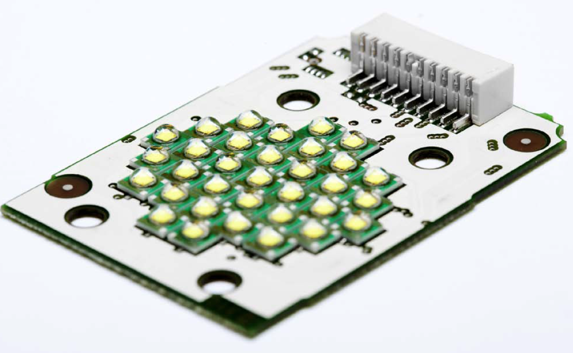
This is where the HSMtec technology demonstrates its advantages: An LED cluster measuring 19 mm in diameter with 30 Cree XLamp LEDs type XB-D and a total power of 100 W acts as reference module. It conforms to the intended Zhaga performance goals of 50 W per module with integrated driver without difficulty, and control electronics can be mounted on the same board as the driver components.
With very similar requirements like Zhaga modules, a 28x28 mm LED array with 33 Cree XLamp XP-E-RGB high-brightness LEDs with 2 W each is already being used in the LED floodlight SpectraWow+ from LDDE which is supposed to redefine additive color mixing. The result is a functional floodlight for stage lighting and architectural lighting with integrated RGB color mixing. It is also available with white light with 3200 K and 5700 K color temperature. Combined with a special honeycomb lens, the floodlight shines very uniformly. Furthermore, undesirable color shadows, common in many LED headlights with single-lens optics, are a problem of the past
Conclusion
The presented technology proves to be reliable and versatile applicable. With more than 8000 failure-free temperature cycles, especially reliable outdoor products can be designed. In addition, the high power densities which are required for Zhaga compliant products can be managed. This is already field-proven by a module with very similar specifications in a demanding application.
