Rethinking the Photometric Data File Format
With increasing computing power, engineering disciplines cannot be imagined without simulations anymore. In lighting, photometric data and electronic processing of this data has become one of the most important tools for luminaire design and lighting design. This data is today provided in IES LM-63 format, a format that meanwhile has come to its limits. P. Eng. (Ret) Ian Ashdown, Senior Scientist at SunTracker Technologies Ltd., explains why the time for a change to a new standard has come and discusses the newly proposed standard and its properties in detail: ANSI/IES TM-33 respectively UNI 1603054.
It has been over 30 years since the first version of the IES LM-63-86, IES Recommended Standard File Format for Electronic Transfer of Photometric Data was published. After three revisions which mainly concerned the file format specification, IES LM-63 still focuses on “old technologies” and does not consider new requirements.
As professional lighting designers, we now have to consider color-changing luminaires, theatrical lighting, human-centric lighting, horticultural lighting, ultraviolet sterilization units, radiant heating devices, and more. We need to consider spectral power distributions, S/P ratios, melanopic and mesopic lumens, radiant and photon intensity distributions, photosynthetically active radiation (PAR), irradiance and photon flux density distributions, color rendition metrics … the list goes on and on (Remark: Photon flux, also commonly referred to as quantum flux, is the rate of flow of photons. Radiant flux, by comparison, is the rate of flow of energy. The energy of a photon is inversely proportional to its wavelength, so quantum flux is not directly comparable to radiant flux).
The LM-63 and EULUMDAT file formats are clearly incapable of characterizing luminaires for these applications. It is therefore time, indeed well past time, to rethink the photometric data file format. It is more than just photometric data, however; it is luminaire optical data that we need to think about.
Brief History of IES LM-63
If you perform lighting design calculations today, you can thank the efforts of the Illuminating Engineering Society’s Computer Committee (IESCC) some thirty years ago. Its members recognized an industry need, and so developed and published IES LM-63-86, IES Recommended Standard File Format for Electronic Transfer of Photometric Data. With the growing popularity of the IBM Personal Computer for business applications, it was an idea whose time had come.
The need was clear: Lighting Technologies (Boulder, CO) had released its Lumen Micro lighting design and analysis software product in 1982, and luminaire manufacturers needed to provide photometric data for their products. For them, IES LM-63 was a god-send in that it established an industry-standard file format.
In keeping with the technology of the time, the file format was human-readable ASCII text, something that could be printed with a dot-matrix printer. It also resulted in files of only a few kilobytes, a definite advantage when data files were transferred by mail on 5-1/4 inch floppy diskettes capable of holding 360 kilobytes of data.
The file format itself revealed something of its origins by limiting line lengths to 80 characters - the width of an IBM Hollerith punch card in the 1960s (Figure 1).
![IBM Hollerith 80-character punch cards (Credits: Wikimedia Commons [1])](https://www.led-professional.com/media/resources-1_articles_rethinking-the-photometric-data-file-format_figure-1.jpg/@@images/image-1280-aaab8a0134007549545e6fd1a1f00f18.jpeg "IBM Hollerith 80-character punch cards (Credits: Wikimedia Commons [1])") Figure 1: IBM Hollerith 80-character punch cards (Credits: Wikimedia Commons [1])
Figure 1: IBM Hollerith 80-character punch cards (Credits: Wikimedia Commons [1])
Three decades later, our personal computers are one thousand times faster, with one million times the memory capacity and ten million times more data storage capacity. Data is transferred by fiber optic cable and satellite links at gigahertz rates … and we are still using IES LM-63 photometric data files!
The “we” of course refers mostly to North America. In Europe, the equivalent file format is EULUMDAT, which was introduced in 1990 for use with Microsoft’s MS-DOS 3.0 operating system. Again, in keeping with the technology of the time, it was also human-readable ASCII text.
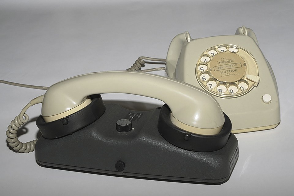
It is a testament to something - exactly what is unclear - that these two file formats have met the lighting industry’s needs for so long. Coming from an era of floppy diskettes and dial-up modems with acoustic couplers (Figure 2), they should have become extinct decades ago (The Chartered Institute of Building Services Engineers in the United Kingdom introduced its CIBSE TM14 file format specification in 1988, but it has since slipped into obscurity).
![Figure 2: "Modern communications technology" - circa 1986 (Credits: Wikimedia Commons [2])](https://www.led-professional.com/media/resources-1_articles_rethinking-the-photometric-data-file-format_figure-2.jpg/@@images/image-1280-aaab8a0134007549545e6fd1a1f00f18.jpeg "Figure 2: \"Modern communications technology\" - circa 1986 (Credits: Wikimedia Commons [2])") Figure 2: "Modern communications technology" - circa 1986 (Credits: Wikimedia Commons [2])
Figure 2: "Modern communications technology" - circa 1986 (Credits: Wikimedia Commons [2])
To be fair, LM-63 was revised in 1991, 1995, and 2002. These revisions, however, at best tweaked the file format specification to resolve various ambiguities and add a few minor features. What we have today is basically what was published in 1986, a time when the pinnacle of lamp technology was the compact fluorescent lamp with an electronic ballast.
If the LM-63 file format has an advantage, it is that it is an ANSI/IES standard that is maintained by an internationally-recognized standards organization. EULUMDAT, on the other hand, is a de facto standard that has been essentially frozen in time since its publication in 1990. Without the authority of a standards organization such as ANSI/IES or CEN (European Committee for Standardization) to maintain the file format, it can never be revised.
Today, the problem is that while LM-63 and EULUMDAT are still useful in terms of characterizing architectural and roadway luminaires, the lighting industry has moved beyond luminous intensity distributions.
An International Standard
Beginning in September 2016, the IESCC initiated a standards development project for the representation of luminaire optical data. Given today’s global trade networks, it was imperative that the standard be international in scope rather than regional or national. Some fifty lighting industry companies and professionals from around the world were therefore recruited to contribute to the project.
Two years later, the effort has succeeded beyond all expectations. The IESCC worked closely with the Italian national standards organization (UNI) Technical Commission CT023, Light and Lighting, to produce two functionally equivalent versions of the standard: ANSI/IES TM-33, Standard Format for the Electronic Transfer of Luminaire Optical Data, and UNI 1603054, Light and Lighting - Specifications for a Format of Photometric and Spectrometric Data Exchange of Lighting Equipment and of the Lamps. As of this writing, the CIE is considering adopting the standard as a joint CIE/ISO publication. In the meantime, CIE Division 1 is establishing a new technical committee to maintain what has become, as intended, an international standard.
For the sake of brevity, the standard will be referred in this article as “TM-33.” However, all information and comments apply equally to UNI 1603054.
BIM Standards
Some North American readers may remember IESNA LM-74-05, Standard File Format for the Electronic Transfer of Luminaire Component Data. The IESCC worked on the development of this document for over a decade prior to its publication in 2005. It was an ambitious effort to combine all aspects of luminaires into a single data file, including far-field photometry, lamp and ballast information, physical geometry, construction materials and finishes, CAD drawings, photographs, and more.
Unfortunately, it was too ambitious. Despite the first release being focused on lamp data, the standard was never adopted by its intended audience of luminaire manufacturers, architects and engineers, lighting product specifiers, photometric testing laboratories, and lighting software developers. Simply put, the lighting industry at the time did not have a need for such a standard.
Today, we might look upon LM-74-05 as being an early example of a specialized building information management (BIM) schema, one that focused on a small subset of typically much larger datasets. (A document schema is conceptually equivalent to a file format specification.) The Green Building XML Schema (gbXML) for BIM applications provides an excellent example.
Quoting from the gbXML Web site:
“The Green Building XML schema, or "gbXML," was developed to facilitate the transfer of building information stored in CAD-based building information models, enabling interoperability between disparate building design and engineering analysis software tools. This is all in the name of helping architects, engineers, and energy modelers to design more energy efficient buildings.”
Unfortunately for the lighting industry, the gbXML schema has an XML “element” called “Photometry”.
The description of the XML:
“Photometry” element reads: “This element has been left open for use with other photometry definitions. Photometric data is required for various forms of lighting analysis. This tag provides a way for the photometric data to be passed. Since this can be done in a variety of ways (iesna LM-63, cibse TM14, EULUMDAT, etc.) a specific format is not being specified.”
Defining a new luminaire optical data format that is compatible with the gbXML and similar BIM schemas therefore serves a clear and present need.
Understanding XML
The advantage of gbXML is that it is based on the international data exchange standard XML (eXtensible Markup Language). The details of this standard are complex and exhausting, but basically every XML document consists of text strings called “elements”.
XML element example:
<name>Alfred E. Neuman</name>
... where the data is surrounded by begin and end “tags.”
These elements can be arranged in a hierarchy, such as:
<person>
<name>Alfred E. Neuman
</name>
<employer>MAD Magazine
</employer>
</person>
In this example, the <person> element is the “parent,” and any elements within it are its “children.”
Building on this simplest of representations, virtually any type of data can be unambiguously represented within an XML document. If a person or computer program reading an XML document encounters an unknown element tag, the element and its children (if any) can simply be ignored.
This, of course, is the problem with including LM-63 or EULUMDAT text files verbatim (i.e., as a multiline text string) within gbXML or similar BIM documents. Yes, it can be done, but the computer program reading the document needs to be able to somehow identify and read these files. Designing TM-33 as an XML document has resolved this problem.
Document Structure
Compared to the simplicity of photometric data files, the TM-33 document schema is relatively complex, with over 240 defined XML elements. However, the majority of these elements are optional. Existing IES LM-63 and EULUMDAT photometric data files can be ported to equivalent TM-33 documents with no loss of information, and with the resultant TM-33 files being not much larger than the original files. With this, TM-33 documents are comprised of four sections: Header, Luminaire, Equipment, and Emitter.
Four sections of an TM-33 document in detail:
Header
The header section includes information that is currently available in LM-63 and EULUMDAT files, such as manufacturer, catalog number, description, and test laboratory, but there are some interesting additions.
Interesting additions of TM-33 documents:
• GTIN
• Unique Identifier
• Reference
• More Information URI
The optional GTIN (Global Trade Item Number) element is an internationally-recognized identification code for trade items. Consumers encounter various forms of GTINs almost every day when they purchase products with barcode labels. A GTIN uniquely identifies the luminaire.
One of the problems with current photometric data files is that there is no version control. If a company reissues photometric data for a product, there is no way of distinguishing between files other than their file creation dates. If the files are copied for any reason, these dates can change. To address this issue, the optional Unique Identifier element identifies the TM-33 document with a Universally Unique Identifier (UUID). While a UUID does not prevent someone from intentionally modifying the document data, it at least solves the problem of multiple files with the same name. Even better, UUIDs (which are commonly used to identify information in computer systems) are for all practical purposes unique, and do not require a central registration authority.
With the introduction of IoT technology, it is becoming increasingly important to keep track of related documents, particularly manuals, for luminaires. There may therefore be one or more optional Reference elements to list the names of these documents. For more volatile information, the optional More Information URI element provides a Uniform Resource Identifier (i.e., a Web address) for further luminaire information.
Luminaire
TM-33 represents the luminaire as an axis-aligned rectangular box or cylinder (FIG. 3) that bounds the actual luminaire geometry. The luminaire section therefore lists the dimensions of this “bounding box” as length, width, and height.
 Figure 3: Luminaire dimensions
It could be argued that more detailed geometric information would be useful, such as ceiling cutout dimensions for recessed luminaires. This, however, is more properly addressed with BIM documents - TM-33 is concerned only with luminaire optical data.
Equipment
The equipment section describes the laboratory instruments used to perform the luminaire optical data measurements.
Lab instruments can include:
• Gonioradiometer (intensity measurements)
• Integrating sphere (flux measurements)
• Spectroradiometer (spectral power distribution measurements)
and detailed information specific to these instruments, such as the gonioradiometer type and spectroradiometer characteristics.
The term “gonioradiometer” is something of a compromise in that the instruments may be designed to measure luminous intensity (i.e. a goniophotometer), radiant intensity (i.e. a gonioradiometer), or photon intensity for horticultural applications (for which there is no accepted instrument name). The only difference between the three types is that the photosensor has different spectral weightings for each one (e.g. V(λ) for luminous intensity).
Emitter
Photometric data files assume that the luminaire includes one or more removable lamps, but this concept does not apply to solid state lighting, which may have removable LED modules or non-removable LED arrays. Moreover, the lamps or LED modules may emit ultraviolet or infrared radiation rather than visible light. For the purposes of TM-33, these are therefore collectively referred to as “emitters.”
Additions to the Usual LM-63 and EULUMDAT Lamp Information
In addition to the usual LM-63 and EULUMDAT lamp information - quantity, rated lumens, input wattage and so forth - the emitter information may optionally include power factor, correlated color temperature (CCT) values, color rendering metric values (Ra and R9 for CIE Colour Rendering, and Rf and Rg for IES TM-30-15 Color Rendition), and scotopic-to-photopic lumens (S/P) ratios. For variable- CCT luminaires, some of these values may need to be expressed as ranges.
One optional but important item is the “Data Generation” element. With photometric data files, it is impossible to know whether the luminous intensity data was measured in a laboratory or the result of a computer simulation. The Data Generation element distinguishes between the two, including whether the measured intensity data has been scaled based on the number of lamps and whether the measurement angles were interpolated. It also provides detailed information on the laboratory accreditation and instrument measurement uncertainties.
Spectroradiometric data
A key ability of the emitter section is to represent the spectral power distribution (SPD) of the emitter. Following IES TM-27-14, IES Standard Format for the Electronic Transfer of Spectral Data, the measured spectral radiant flux is reported for each wavelength.
Most SPDs are reported with constant wavelength intervals (e.g. 5 nm), but TM-33 does not impose such a restriction. Consequently, both continuous and line emission spectral features can be represented with arbitrary wavelength precision.
Intensity data
With photometric data files, most of the data represents the luminous intensity measurements for vertical and horizontal angles. The same is true for TM-33 documents in the emitter section except that, depending on the application, the intensity measurements may be based on luminous flux, radiant flux, photon flux, or spectral radiant flux.
|
Intensity |
Metric |
Typical Applications |
|
Luminous |
lumens per steradian (candela) |
Architectural and roadway lighting |
|
Radiant |
watts per steradian |
UV sterilization and radiant heating |
|
Photon |
micromoles per steradian per second |
Horticultural lighting |
|
Spectral |
watts per steradian per nanometer |
Angular color uniformity |
Table 1: Intensity measurement data, type and application
Both radiant and photon intensity are measured over a specified range of wavelengths. When photon intensity is measured over the range of 400 nm to 700 nm, it is equivalent to photosynthetically active radiation (PAR).
Spectral radiant intensity distributions assign an SPD to each measurement. The distributions are useful for representing the variation in color with varying view angle, such as occurs with phosphorcoated white light LEDs.
Each intensity measurement is expressed as (for example):
<IntensityData horz="90.0" vert="65.0"> 109
</IntensityData>
By explicitly expressing the vertical and horizontal angles for each measurement, there is no requirement for the data to be organized as a two-dimensional array of vertical angles and horizontal planes. This is important because some robotic gonioradiometers are capable of measuring angular positions on a geodesic sphere and other complex angular patterns.
Application-distance radiometry
Application-distance photometry, also known as “near-field photometry,” was developed in the 1990s to represent the illuminance distribution on a ceiling above an indirect linear fluorescent luminaire. The laboratory measurement process was documented in IES LM-70-00, Guide to Near-Field Photometry, but it was never adopted by the lighting industry.
Today, however, there is an obvious application: linear LED strips used in vertical farms, where trays of leafy green vegetables are grown within half a meter of the luminaires. As of this writing, the IES and the American Society of Agricultural and Biological Engineers (ASABE) are collaborating on the development of a standard for application-distance radiometry measurements. The standard will also be applicable to ultraviolet sterilization units and infrared ovens.
TM-33 fully supports applicationdistance measurements for illuminance, irradiance, photon flux density, and spectral irradiance, with multiple planes oriented at any angle as required.
Channels
A luminaire may have multiple emitters with different SPDs, such as a theatrical luminaire with red, green, blue, and amber LEDs. If the intensity of each emitter can be independently dimmed without significantly changing the spatial intensity distribution, a “channel multiplier” can be applied to the channel intensity distribution to represent the luminaire intensity distribution when the channel is fully enabled to produce “white” light with the specified CCT. (The sum of the channel multipliers must be equal to unity.)
Emission areas
Discomfort glare metrics such as the CIE Unified Glare Rating (CIE 117-1996) require knowledge of the luminous areas of luminaires as seen by the observer. TM-33 supports the representation of one or more rectangular or elliptical “emission areas” on any side of the luminaire bounding box or cylinder.
Emitter center
The “Emitter Center” element specifies the horizontal and vertical offsets of the presumed point source from the geometric center of the luminaire bounding box or cylinder.
Regulatory values
Measurement values presented in a TM-33 document can be one of three types: measured; rated; or nominal. A “rated” value is the value of a quantity used for specification purposes, established for a specified set of operating conditions of the product, while a “nominal value” is an approximate quantity value used to designate or identify the product. If a particular regulatory element (e., “Input Watts”) is absent, its values are assumed to have been measured or calculated from measured data.
Custom data
The “Custom Data” element provides a means of including custom data. For example, a company or government agency may require additional data that cannot be represented within the base TM-33 document. Multiple custom data elements are allowed, each one including a name element (e.g., “Italian CAM”), a UUID element to uniquely identify the parent “Custom Data” element, and an arbitrary sequence of XML elements to represent the custom data itself. Unless the software reading the TM-33 document explicitly recognizes the custom data element, the element and all of its children elements will be ignored.
Summary
If the above description of the TM-33 document schema seems rather complex, that is because it is. While both the IES LM-63 and EULUMDAT file formats are specified using one to several pages, the ANSI/IES TM-33 and UNI 1603054 document specifications run to 70 pages or more.
Most of the XML elements comprising a TM-33 document, however, are optional. Porting an LM-33 or EULUMDAT data file to the TM-33 format results in documents that are not much larger than the original files, and with no loss of information. On the other hand, newly-generated TM-33 documents provide for a wealth of useful information for luminaires that can (and likely should) be included.
Finally, the TM-33 document schema was intentionally designed to be extensible. Whatever future additions may be made to the schema, they will always be completely backwards-compatible with the base document.
The lighting industry currently relies on photometric data file formats that were developed three decades ago. The TM-33 document schema has been designed for today and the future.
References:
[1] Wikimedia Commons: https://commons.wikimedia.org/wiki/File:Card_puncher_-_NARA_-_513295.jpg
[2] Wikimedia Commons: https://upload.wikimedia.org/wikipedia/commons/thumb/e/e0/AcousticCouplerAK2000Tel.jpg/1024px-AcousticCouplerAK2000Tel.jpg
