Safety Issues for LED Drivers with PWM Operation Modes by Product Approvals Ltd.
In many cases LED drivers manage their output power with PWM controlled switched mode power supply-topologies. The output voltages are filtered and normally DC voltages with low ripple apply at the output connectors of LED drivers. During dimming these circuits can behave very differently and therefore safety issues may arise. Siegfried Luger, CEO at Luger Research e.U. and John Showell, Product Safety Consultant at Product Approvals Ltd. have a closer look at those operation modes and the requirements on voltage limits.
LED lighting technologies are developing very quickly. As the light-sources themselves evolved, new sophisticated and enhanced electronic concepts were developed to drive and control LEDs. These developments are very important for fulfilling market requirements but safety and standardization aspects are lagging behind. One issue related to LED drivers concerns the output voltage limitations for LED drivers. The following considerations summarize the latest developments and point out possible safety issues.
Basic LED Driver Topology
LED drivers can be categorized into DC to DC converters and AC to DC converters. Where AC to DC converters are concerned, in most cases, they operate directly from the mains (e.g. 240 Vrms / 50 Hz). AC to DC converters for mains applications consisting of an EMI filter, a bridge-rectifier and a single-converter stage, are mostly built up as a flyback converter to transform the rectified AC voltage into a constant DC current to perform the powerfactor-correction and to isolate the output LED circuit from the mains. Finally the output current is also rectified and the energy is stored in an output capacitor (Figure 1). LED strings in serial or in serial/parallel are connected to the LED driver output poles.
 Figure 1: Typical AC to DC LED driver topology with a single-stage flyback converter
The output stage of such an AC to DC converter is galvanically isolated through the flyback-transformer. Therefore the feedback circuit has to be isolated to sense the LED string cur-rent. This might be done through an optocoupler but more advanced sensing schemes use the primary side of the transformer or an additional sensing winding to detect the output LED current.
The switching frequency of the flyback converter may vary between 10 kHz up to some MHz. To control the output power/current for dimming the light output, PWM schemes are used.
Nowadays, to reduce flickering and stroboscoping effects on human eyes, the PWM frequencies are chosen above some hundred Hertz (e.g. 300-500 Hz). Under standard operation conditions the PWM signal will not be seen at the output, because of the rectifying and buffering output circuit. Figure 2 shows the output voltage (Ch2) as a DC voltage with a small part of AC ripple.
 overlaying with a small part of AC ripple voltage (approx. 4 Vpp). Ch1 shows the high-frequency ripple-current from one output pole to earth (10 mA/Div). Time base is 20 ms/Div") Figure 2: DC output voltage of an LED driver (Ch2, approx. 55 VDC) overlaying with a small part of AC ripple voltage (approx. 4 Vpp). Ch1 shows the high-frequency ripple-current from one output pole to earth (10 mA/Div). Time base is 20 ms/Div
Figure 2: DC output voltage of an LED driver (Ch2, approx. 55 VDC) overlaying with a small part of AC ripple voltage (approx. 4 Vpp). Ch1 shows the high-frequency ripple-current from one output pole to earth (10 mA/Div). Time base is 20 ms/Div
Possible Safety Issue - Chopped DC
Assuming that the LED driver and the output stage are designed as an SELV (Safety Extra Low Voltage) converter it is allowed to touch the output lines, bridging the positive to the negative pole of the output with the human body impedance.
When operating in dimmed modes (power reduction), the energy delivered to the output storage capacitor is reduced. Touching the output lines under this condition can lead to a change in the output voltage signal from a DC voltage to a chopped DC voltage in which the PWM frequency can be seen at the output (Figure 3). This might happen especially when sensing the output current similar to the concept shown in figure 1. Bypassing the sensing resistor with the load of the human body would not lead to a regulation of the LED driver system.
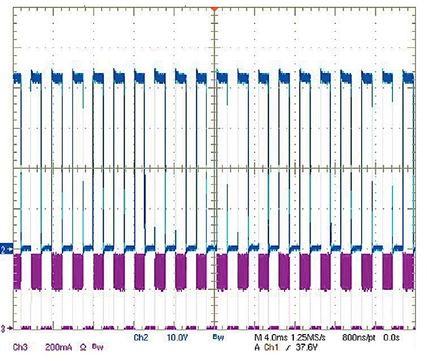
 Figure 3: Measurement of an LED driver output under 2kOhm load and 50% duty-cycle. Ch2 showing the voltage above the output terminals. Ch3 showing the LED current
Under this condition critical operation modes for these LED drivers may occur when the driver is not designed for additional low ohmic loads, e.g. too low capacitor values and/or insufficient regulation algorithms.
The main topic is that the change from “pure DC” output voltages to alternative voltages, here chopped DC signals means that the safety voltage limits for these drivers may change automatically to lower values due to the change of the voltage signals!
Backgrounds - Human Body Model
There are different impedance models for the human body available and also defined in international standards. The model shown in figure 4 known as Perception / Reaction network is defined by a resistive load of 1.5 kΩ and 0.5 kΩ in series and a capacitor of 220nF in parallel to the 1.5 kΩ resistor. The input impedance at 50 Hz is 1,990 Ω, at 500 Hz 1,433 Ω and it drops down to 476 Ω at 1 MHz. The output stages of an SELV LED driver, therefore, might be bridged with a human body impedance between 1.5-2.0 kΩ under real conditions, when touching the output lines. This “load” is responsible for changing the output signal from a DC voltage to a chopped-DC voltage.
. The human body model with perception / reaction network is the most realistic test method, but usually just applied if a standard test with 50 kOhms fails") Figure 4: Perception / Reaction network (according to IEC 60990, 1999 - Figure 4). The human body model with perception / reaction network is the most realistic test method, but usually just applied if a standard test with 50 kOhms fails
Figure 4: Perception / Reaction network (according to IEC 60990, 1999 - Figure 4). The human body model with perception / reaction network is the most realistic test method, but usually just applied if a standard test with 50 kOhms fails
The touch current limits are measured across the 500 Ω resistor Rb (voltage U1). The measuring network R1 and C1 showing in figure 4 are used for a weighted touch current. So the measuring voltage U2 does include frequency ependencies as well. The variation of the threshold of perception, for example, is increased by the factor of 1.5 between 50/60 Hz and 500 Hz, the base operation frequency of PWM drivers (see IEC TS 60479- 2:2007 - Figure 1 for further details). Earlier studies, as shown in figure 5, were the basis and documented the principle relationship between the thresholds and the frequency.
") Figure 5: Let-go thresholds and dangerous current limits as a function of frequency (C.F. Dalziel, “Electrical Shock”, Advances in Biomedical Engineering, edited by J. H. U. Brown and J. F. Dickson III, 1973, 3, 223-248)
Figure 5: Let-go thresholds and dangerous current limits as a function of frequency (C.F. Dalziel, “Electrical Shock”, Advances in Biomedical Engineering, edited by J. H. U. Brown and J. F. Dickson III, 1973, 3, 223-248)
Safety Issues - Consequences of Changing the Mode of Operation
As described above LED drivers might change their mode of operation when touching the output terminals. With the human body model this behavior can be tested with LED drivers, bridging the output. The question which then arises is: “What does this mean to safety?”
There are various US and EN standards which answer this question. In regards to safety the maximum or peak voltage level is interesting, because of the ability of the voltage to drive current through the body - which is the mechanism of the electric shock. There are some differences between voltage magnitudes for DC and AC signals. Peak voltage is commonly referred to, such as quoted in the LED professional Review (LpR) article Issue 39, e.g. 42.4 Vpeak (30 Vrms) is a common UL figure but not universal across UL standards. The differences come in because of US UL standards and those of UL standards which are based on an IEC standard and have some commonality with EU voltage levels.
The UL standard groups for LEDs recognize the guidance needed for certain scenarios. As such, UL 8750 (other UL end-product standards may apply) covers products intended for installation on branch circuits of 600 V or less. UL also noted that many LED products are designated for Class 2, which refers to supply characteristics specified in Article 725 of the National Electric Code (NEC). Please note that in brief, Class 2 circuits are isolated and have maximum voltage ratings of 60 VDC, 30 Vrms, maximum current ratings of 8 A and maximum power ratings of 100 W. Electrical systems obeying Class 2 specifications may afford additional design freedom that includes the selection of material to address flammability concerns and accessibility of other circuits. Such affordability makes Class 2 compliance popular among LED luminaire designers and manufacturers. Table 1 shows reduced maximum voltages for wet locations compared to dry/damp locations defined in UL 8750 for the risk of shock.
 For a combined ac + dc waveform, the wet location voltage limit shall be the non-sinusoidal ac limit where the dc voltage is no more than 10.4 V, and shall be (16 + 0.45*dc voltage)V where the dc voltage is greater than 10.4 V. The dry and damp location voltage limit shall be twice these amounts b) If the peak-to-peak ripple voltage on a DC waveform exceeds 10 percent of the DC voltage, the waveform shall be considered a combined waveform per footnote above c) DC waveforms interrupted at frequencies between 10-200 Hz shall be limited to 24.8 V in dry and damp locations, and 12.4 V in wet locations") Table 1: Reduced maximum voltages for wet locations compared to dry/damp locations defined in UL 8750 for the risk of shock:
Table 1: Reduced maximum voltages for wet locations compared to dry/damp locations defined in UL 8750 for the risk of shock:
a) For a combined ac + dc waveform, the wet location voltage limit shall be the non-sinusoidal ac limit where the dc voltage is no more than 10.4 V, and shall be (16 + 0.45*dc voltage)V where the dc voltage is greater than 10.4 V. The dry and damp location voltage limit shall be twice these amounts
b) If the peak-to-peak ripple voltage on a DC waveform exceeds 10 percent of the DC voltage, the waveform shall be considered a combined waveform per footnote above
c) DC waveforms interrupted at frequencies between 10-200 Hz shall be limited to 24.8 V in dry and damp locations, and 12.4 V in wet locations
The values for chopped DC or interrupted DC signals as proposed in UL 8750 (Table 1) are based on studies done by W. B. Kouwenhoven in 1936. He found out that the peak voltage limits for fibrillating currents at 60 Hz has to be lowered by the factor of 1.69 compared to alternating currents.
50 Vrms * √2 = 70.7 Vpeak
70.7 Vpeak/1.69 = 41.7 V
(max. interrupted DC voltage)
A. Mörx who found out that the reduction of the human body impedance has to be considered for higher voltages performed a further analysis for safety voltage limits.
According to IEC TS 60479-1:2005 the impedance at 50 VDC is 2900 Ω and drops down to 1625 Ω at 125 VDC. These recognitions are not covered in details within this report but may be important for further analysis.
Table 2 shows the different voltage limits in a comparison between the UL and IEC for 120 VDC and 60 VDC levels and gives indications for possible “new voltage limits” which are in consideration right now. The 120 VDC value shown in table 2 is valid for single pole touchable SELV. It is important to recognize that an SELV LED driver, for example, designed with 60 VDC voltage limit, would fall immediately out of the safety limits when changing the output mode from DC to chopped DC because the limit for DC falls from 60 V to 24.8 V (frequencies between 10 - 200 Hz)!
)") Table 2: Column A shows the SELV limit voltages acc. IEC 60449:1973 calculated based on Kouwenhoven studies. Column B shows the UL proposal for Class-2 power supplies in reference to NFPA 70 - 2011 (Note: The 30 Vrms limit in UL 8750 corresponds to 25 Vrms limit according to EN 61347-1 (10.4))
Table 2: Column A shows the SELV limit voltages acc. IEC 60449:1973 calculated based on Kouwenhoven studies. Column B shows the UL proposal for Class-2 power supplies in reference to NFPA 70 - 2011 (Note: The 30 Vrms limit in UL 8750 corresponds to 25 Vrms limit according to EN 61347-1 (10.4))
Higher frequencies would help because the limits for higher frequencies go up. On the other hand, new research on the human body model also works against this. Therefore, it’s a very undefined and unclear situation. In general, it can be stated that the change from DC to AC will lead to a reduction of the limits to some extent. This is an important issue for designing safe LED drivers for the future.
Conclusion
Output lines of SELV/Class-2 LED drivers are allowed to be touched. Depending on the operation mode, the LED driver design and the used component values, LED drivers may “switch” from DC output mode into AC output modes, mostly with chopped-DC signals. Since AC voltage limits are below the DC voltage limitations, the safety requirements of these drivers are changing with the operation mode. On the other hand, LED drivers operating with PWM control are using higher frequencies then the standards normally cover. Instead of DC, 50 or 60 Hz they are operating the PWM at some hundreds of Hertz (e.g. 500 Hz).
The global discussions going on about these limits are important in respect to safety to cover all critical conditions which might occur in applications. For manufacturers of LED drivers it is important to know that the limits for PWM controlled LED drivers might be reduced and tested under given conditions and that the limits might be lowered against the pure DC limits by a factor of 2.4 - 2.9. New designs should take care of this fact and even if further investigations have to be made to define the correct limits.
References:
[1] http://www.comm-2000.com/
[2] Mr. Bahram Barzideh, PDE Manager, Lighting from Tom Blewitt’s group in Melville, New York
[3] Wirkungen des elektrischen Stromes auf Menschen und Nutztiere - IEC/TS 60479-1:2005 + Corrigendum Oktober 2006 (VDE V 0140-479-1)
[4] Berührungsspannungen für Gleichstrom, Mörx, August 2012
[5] Electrical Safety, Walter H. Olson, 2008
[6] Guidelines for Limiting Exposure to Time-Varying Electric, Magnetic, and Elekctromagnetic fields (up to 300 GHz), Health Phys 75(4):442; 1998
[7] Berufsgenossenschaftliche Vorschrift für Sicherheit und Gesundheit bei der Arbeit. Unfallverhü-tungsvorschrift - Elektromagnetische Felder, 2001
[8] Normen für DC-Technik / DC-Netze, Dirk Barthel, DKE, 2012
[9] Touch Current Basics, Ronald Vaickauski, UL, 2010
[10] IEC 43/191/CDV, IED 62493 Ed.2: Assessment of lighting equipment related to human exposure to electromagnetic fields
[11] Technical Report IEC/TR 62493-1 Ed.1 Part 1: Results of the EMF measurement campaign from the VDE Test and Certification Institute and ZVEI, the German Electrical and Electronic Manufacturers’ As-sociation
[12] IEC 62493 Edition 1.0 2009-12
[13] Proceedings of the IEEE, William B. Kouwenhoven, Vol. 97, No.12, December 2009
[14] IEEE Standard for Safety Levels with Respect to Human Exposure to Radio Frequency Electromag-netic Fields, 3 kHz to 300 GHz
[15] Maximum Permissible Touch and Step Voltages Assessment in High Voltage Systems (>1 kV)
[16] Residual Current Devices in LV, Schneider Electric, 2006
[17] Personenschutz und Fehlerstromschutzschalter für LV DC-Netze, Rik W. De Docker, 2012
