Smart Design of Freeform Micro-Optical Elements for Thin Direct-Lit Luminaires
LpR 69 Article, page 64: Direct-lit LED luminaires consist of LED arrays. In order to achieve homogenous light distribution a diffuser sheet is placed at a certain height above the LED array. Usually the distance between the LEDs and the diffuser has to be greater than the distance between the LEDs on the array. To overcome this limitation, additional optical elements like freeform lenses are necessary. Christian Sommer, scientist at the Institute of Surface Technologies and Photonics of the Joanneum Research Forschungsges.m.b.H and his colleagues, Claude Leiner, Ladislav Kuna, Paul Hartmann and Franz P. Wenzl propose a smart design concept for an extremely flat, direct-lit lighting system, making use of mask-less laser direct write lithography.
Common LED based direct-lit luminaires for general lighting applications use LEDs as light sources, which are placed at a certain distance in a regularly arranged array. In order to achieve homogenous light distribution a diffuser sheet has to be placed on the outcoupling side at a certain height above the LED array. The required height is determined by the distance between the LEDs. For this so-called DHR (distance (of the LEDs) to height (of the diffuser sheet placement) ratio) values of 1 are hardly achievable. To overcome this limitation additional optical elements like freeform lenses are necessary.
In this contribution we discuss a smart design concept for an extremely flat, direct-lit lighting system. It is characterized by an improved distance (LEDs) to height (diffuser sheet) ratio compared to diffuser sheet only-approaches and a smaller thickness compared to common freeform approaches. For this demand we designed very thin freeform lenses with a maximal height of 60 μm that allow to maintain a uniform illumination in a flat direct-lit backlight using an LED-array with a comparably large distance between the individual LEDs. The concept emphasizes the use of mask-less laser direct write lithography for the costeffective fabrication of the thin freeform micro-lens array.
Introduction
Light sources based on light emitting diodes (LEDs) have a lot of advantages in comparison with their conventional counterparts like incandescent or compact fluorescent lamps, which range from lifetime, reliability, energy saving to new potentials for system integration because of their compact sizes [1,2]. As a consequence, LED based luminaires nowadays have found their way into signage, display backlight, automotive lighting, general lighting and architectural lighting applications.
Still, research on LEDs and LED based luminaires has not come to an end yet and there are a lot of challenges ahead for the ongoing improvements of device efficiency, white light quality, but also luminaire design. In this regard, in the following we extend our previous discussion [3] on a design concept for a direct-lit luminaire for general and architectural lighting.
As discussed in [3], such a set-up for a direct-lit luminaire has a close relationship to the more recognizeddirect-lit backlight for liquid crystal displays (LCD) used in the premium segment of television (TV) sets.
The possibilities for a homogeneous luminance and a very flat construction in combination with a large display size are the reasons why LED based light sources have become very attractive for the backlight unit (BLU) of LCD television sets. On the other hand, these potentials are also very appealing for a direct-lit luminaire aiming at general and architectural lighting applications. Usually, the LED light sources of a BLU are arranged in an array and the denser the LED dice are packed the higher is the uniformity of the irradiance on a target plane. Still, the packaging density is limited by the cost (due to a larger amount of LED dice needed with increasing density), the available space and thermal issues.
Therefore, research activities for the design of direct-lit BLUs on the one hand focus on large-scale uniform illumination, and on the other hand on an increased distance between the individual LEDs. The research of the last several years has investigated different LED arrangements and the superposed illumination / irradiance of the LEDs on a certain target plane, e.g., for achieving a homogenous illumination for a rotational symmetric illuminance of a single LED [4,5]. However, the optimal arrangement alone is not sufficient for achieving both a uniform illuminance and a thin BLU. It is desirable that the ratio of the distance between two LEDs and the height (or the thickness) of the BLU, i.e. distance-height ratio (DHR), is high. Increasing the distance between the LEDs of the regular LED-array by keeping the target plane at a constant height is only possible with additional optics. Several researchers have investigated freeform optics in this context [6-8]. The related strategies e.g., rely on a freeform optic for a single LED die which generates a uniform square shaped irradiance distribution with a certain width d. Using an array of individual freeform optical elements with such a configuration allows to generate a uniform irradiance distribution on the target plane, for example on a diffuser element, which transforms the uniform irradiance distribution into a uniform radiance. With such a concept, a large area backlight with a size of several square meters and a uniform luminance comprising a high DHR value of up to 3 can be realized.
These properties are what a direct-lit luminaire would make also very appealing for general and architectural lighting: Large size area, homogeneous luminance, high efficiency, a tuneable brightness, very thin height with a high DHR value. All these desirable properties of LCD displays are also valid for general lighting luminaires and can be derived from strategies developed in this regard. While the freeform optic generates the uniform irradiance at the target plane the diffuser sheet allows for angular mixing of the light so that a uniform luminance can be obtained. High DHR values are desirable because for a specific area of the luminaire a lower number of individual LEDs would be needed, which reduces the costs and lowers the electrical power needed. On the other hand, when keeping the number of LEDs fixed, a higher DHR value allows decreasing the thickness of the luminaire facilitating its integration, e.g., into walls for indoor lighting.
In the following, we extend the discussion on our recently presented design scheme for calculating thin freeform optical elements with an effective height of about 60 μm for a direct-lit luminaire with a high DHR value and an effective height of 10 mm, i.e. height of the target plane relatively to the LEDs. In particular, we discuss non-rotationally symmetric FF elements, which are of relevance in order to avoid the overlapping of the irradiance distributions of the individual elements. Figure 1: Schematic of a direct-lit luminaire concept with flat freeform optics for achieving a homogeneous irradiance on the target plane, at which a diffuser sheet is placed
Freeform Design Procedure
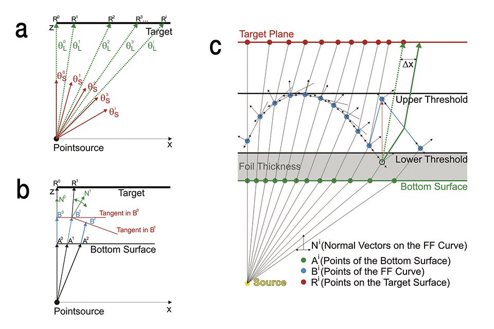
The design procedure for the freeform (FF) optical elements used in this contribution has been published in more detail elsewhere [3]. Briefly, it is based on a two dimensional approach by applying Snell’s law in a ray mapping scheme, which is outlined in figure 2. The FF algorithm enables the determination of a complex optical surface in a sequential process, which allows to transform an arbitrary angle dependent radiant intensity distribution IS(θ) of a light source into a calculated angle dependent radiant intensity distribution IL(θ) which is generating the desired irradiance distribution when illuminating the target plane [8]. In other words, the ray mapping scheme correlates rays emitted by the light source with calculated points R on the target plane (Figure 2a). This allows the design of an optical surface which refracts the emitted rays towards the calculated points R (Figure 2c).
In order to find an optical element which is capable to fulfil this condition, the radiant intensity distributions IL(θ) and IS(θ) are discretized into M rays with different propagation angles θLi and θSi respectively, with i = 1, 2,…, M. By this, the points Ri on the target plane can be determined (Figure 2a). The rays emitted from the source must hit these points to create the desired irradiance distribution on the target plane. The points Bi, which are defining the FF surface, are calculated in a sequential process by determining the surface normal vectors Ni in a way that, according to Snell’s law, the rays are refracted towards their corresponding points Ri on the target plane (Figure 2b). After defining the A° B° and N° as starting parameters the sequential process is composed of three iterative steps (Figure 2b).
The three iterative steps from figure 2b:
• Determining the position of the point Ai by intersecting the i-th ray with the
bottom surface and calculating the change of the propagation direction by
Snell’s law
• Determining the position of the Point Bi by intersecting the tangent
corresponding to the point Bi-1 with the actual ray refracted at point Ai
• Calculating the normal vector Ni in Bi in a way that the actual ray refracts
towards the point Ri on the target plane
 of the source (a). Scheme of the sequential FF algorithm to calculate the points Bi and Ai, which are determining the top and the bottom curve of the FF element (b). Schematic illustration of the functionality of the implemented transformation algorithm when a point Bi falls below the lower threshold value (c)") Figures 2a-c: Illustration of the discretization of the radiant intensity distribution IS(θ) of the source (a). Scheme of the sequential FF algorithm to calculate the points Bi and Ai, which are determining the top and the bottom curve of the FF element (b). Schematic illustration of the functionality of the implemented transformation algorithm when a point Bi falls below the lower threshold value (c)
Figures 2a-c: Illustration of the discretization of the radiant intensity distribution IS(θ) of the source (a). Scheme of the sequential FF algorithm to calculate the points Bi and Ai, which are determining the top and the bottom curve of the FF element (b). Schematic illustration of the functionality of the implemented transformation algorithm when a point Bi falls below the lower threshold value (c)
In order to create very thin FF lenses, we implemented an additional transformation algorithm directly in the sequential process of calculating the FF curve, which allows us to design flat FF lenses by defining two threshold values which define the minimal and the maximal height of the Bi points. The distance between the bottom surface and the lower threshold value therefore corresponds with the thickness of the thin foil (Figure 2c) and the distance between the lower and the upper threshold values defines the height of the FF structure. In case that the height of a point Bi drops below the lower threshold value during the sequential process, the height is artificially adjusted and the sequential process is continued with the adjusted point Bi (Figure 2c). With this measure the calculated FF elements can be restricted to a very flat design (e.g. a maximum of 60 μm), which can be fabricated on a thin foil and enables the use of cost-effective manufacturing methods like gray-scale laser lithography for mastering and roll-to-roll processing for large area manufacturing of the optical elements.
The determined points Ai and Bi are defining a bottom and a top profile of the FF lens and can be transformed into a three dimensional (3D) object by rotating the profile around the perpendicular z axis for 360°. However in this way only rotationally symmetrical irradiance distributions can be generated on the target plane. In order to extend this concept to irradiance distributions with a rectangular shape the 3D FF object has to be “segmented” into different slices with a constant azimuth step size α.
In figure 3 the process for creating such a segmented FF element for a non-rotationally symmetrical irradiance distribution is illustrated. The shape of the irradiance distribution is divided by a predefined number of swept profiles into different slices. The length of the slices depends on the shape of the irradiance distribution and the number of slices depends on the segmentation angle α. In the next step the FF algorithm is conducted for every slice separately, creating different FF curves for each slice. Rotating these different FF curves around the center (by the azimuth step size α) allows to generate 3D segments of the FF object. After the last step the whole FF object is composed of these different segments.
 Figures 3: Schematic illustration for creating a 3-dimensional FF element that gives reason for a rectangular irradiance distribution on the target plane
Results and Discussion
In this section Ray-Tracing (RT) simulation results of different FF elements are shown to illustrate the design concepts discussed in section 2.
Figures 4a, 4b and 4c show the top view of flat FF elements composed of 98 segments. These FF elements are designed to generate a square shaped irradiance distribution on a target plane in a distance of 10 mm, using a 0.5x0.5 mm² LED chip with a Lambertian radiant intensity distribution. The FF elements are considered to be placed on a 0.5 mm thick foil with a refractive index of 1.517 and a distance of 1 mm between the bottom surface of the foil and the emitting area of the light source.
 designed for generating an irradiance distribution with a square shape on a target plane (a). Corresponding irradiance distribution on the target plane, determined by RT simulations (d). 3D Model of a flat segmented FF element (98 segments) designed for generating a uniform irradiance distribution with a square shape on a target plane (b). Corresponding irradiance distribution on the target plane, determined by RT simulations (e). 3D Model of the flat segmented FF element (98 segments) used in b with the FF element placed on a diffuser foil (c). Corresponding irradiance distribution on the target plane, determined by RT simulations (f). Cross section of the shortest and the longest segments of the flat segmented FF elements of b and c (g)") Figures 4a-g: 3D Model of a flat segmented FF element (98 segments) designed for generating an irradiance distribution with a square shape on a target plane (a). Corresponding irradiance distribution on the target plane, determined by RT simulations (d). 3D Model of a flat segmented FF element (98 segments) designed for generating a uniform irradiance distribution with a square shape on a target plane (b). Corresponding irradiance distribution on the target plane, determined by RT simulations (e). 3D Model of the flat segmented FF element (98 segments) used in b with the FF element placed on a diffuser foil (c). Corresponding irradiance distribution on the target plane, determined by RT simulations (f). Cross section of the shortest and the longest segments of the flat segmented FF elements of b and c (g)
Figures 4a-g: 3D Model of a flat segmented FF element (98 segments) designed for generating an irradiance distribution with a square shape on a target plane (a). Corresponding irradiance distribution on the target plane, determined by RT simulations (d). 3D Model of a flat segmented FF element (98 segments) designed for generating a uniform irradiance distribution with a square shape on a target plane (b). Corresponding irradiance distribution on the target plane, determined by RT simulations (e). 3D Model of the flat segmented FF element (98 segments) used in b with the FF element placed on a diffuser foil (c). Corresponding irradiance distribution on the target plane, determined by RT simulations (f). Cross section of the shortest and the longest segments of the flat segmented FF elements of b and c (g)
Figure 4g shows a cross section of the foil (bottom surface blue line, top surface green line) of the foil as well as the calculated FF curves of the shortest (red line) and the longest (dotted blue line) of the segments of the FF element shown in figures 4b,c.
Due to the transformation algorithm applied in order to maintain a very low height, the calculated segments of the FF elements are showing a different number of “teeth” depending on how many times the curve dropped below the lower threshold value during the sequential calculation process. However, due to the transformation algorithm the maximal thickness of the different segments is not surpassing 60 μm (Figures 4a-c).
The FF algorithm applied is based on a two dimensional approximation. For this reason the FF elements can only affect the θ propagation direction of the rays. On the other hand the individual segments are redistributing the same radiant intensity of the light source on different areas due to the different lengths of the slices, which causes an inhomogeneous irradiance distribution (Figure 4d).
To encounter for this issue, the amount of radiant intensity collected by each segment was adjusted in a way that each segment generates the same absolute irradiance value on the target plane (Figure 4e). Figure 4e shows the irradiance distributions (determined by RT simulations) on the target plane, generated by the FF element of figure 4b. As one can see, due to this correction, the FF element is generating now uniform irradiance distributions within the target area. On the other hand, the amount of radiant intensity which is not collected by the FF elements is causing an unwanted intensity distribution outside of the target area (Figure 4e), which will affect the neighbouring intensity distributions when using the FF elements in an array.
To encounter this issue, the FF element of figure 4b was placed on a diffuser foil (Figure 4c) having a Lambertian scattering properties in order to redistribute rays which are not refracted at the FF element randomly on the target plane. Directly beneath the FF elements, the foil has no diffusing properties. As one can see from figure 4f, which is showing the simulated irradiance distribution on the target plane, the diffuser foil is redistributing the unwanted intensity distribution outside of the target area. In order to show the capability of this approach for a direct-lit lighting application, 4x4 FF elements in accordance with the design of figure 4c were arranged together in a square shaped array on a scattering foil which has a thickness of 0.5 mm.
 Figure 5: Schematic sketch of the direct-lit luminaire showing the arrangement of the relevant components and the dimension of the box
Figure 5 illustrates a simulation model of a 64.9x64.9 mm² directlit luminaire box with a height of 10 mm. The top side, the front side wall and one half of the scattering foil were made transparent in the illustration, to facilitate the understanding of the geometrical arrangement of the different optical components of the simulation setting. The bottom side of the luminaire box is composed of a printed circuit board (PCB) with a square shaped LED array. The surface of the PCB was considered to be covered with a resist that has Lambertian scattering properties (reflectivity 85%) for incident rays.
The scattering foil with the FF elements is placed in a distance of 1 mm from the LEDs. The arrangement is in a way that the centers of the FF elements are aligned with the centers of the single LED surfaces to generate a uniform irradiance distribution on the top surface of the box, which is placed 10 mm above the light sources. The dimensions of the LED dice were chosen to be 0.5x0.5 mm² with Lambertian radiant intensity distributions. The distance between the LED dice as well as the FF elements were set to be 16.2 mm, resulting in a DHR of 1.62 for the simulated direct-lit lighting application.
Figure 6 shows the simulated irradiance distribution on the target plane for this simulation setting with (Figure 6a) and without (Figure 6b) the scattering foil with the attached FF elements. As one can see the irradiance distribution generated with the scattering foil containing FF elements shows a very good degree of uniformity on the target area. figure 6b shows a reference simulation of the direct-lit luminaire assuming that no optical elements are applied between the light sources and the top side of the box. The irradiance distribution of the reference simulation clearly shows intensity peaks at the positions of the light sources and would give reason for an inhomogeneous radiance distribution of the direct-lit luminaire box.
. Simulated irradiance distribution on the target plane without any optical element (b)") Figures 6a&b: Simulation result of the irradiance distribution on the target plane using the diffuser foil with FF elements (a). Simulated irradiance distribution on the target plane without any optical element (b)
Figures 6a&b: Simulation result of the irradiance distribution on the target plane using the diffuser foil with FF elements (a). Simulated irradiance distribution on the target plane without any optical element (b)
Conclusions
In this contribution a two dimensional FF approach for calculating thin FF elements for lighting applications, e.g., for the use in direct-lit luminaire boxes, was presented. The proposed FF algorithm allows the calculation of FF elements refracting the radiant intensity of LEDs into uniform irradiance distributions with arbitrary shape. Furthermore a threshold value was included in the calculation algorithm enabling the control of the maximal height of the calculated FF elements.
In this way it was possible to calculate a FF element with a thickness of about 60 μm redistributing the radiant intensity of a 0.5x0.5 mm² LED light source into a square shaped irradiance distribution on a target plane in a distance of 10 mm. By arranging 4x4 of these FF elements in a shaped array on a scattering foil with a thickness of 0.5 mm a direct-lit luminaire box with a DHR of 1.62 was simulated which showed an irradiance distribution with a very good degree of uniformity on the top side. A direct comparison with a simulation of a direct-lit luminaire box without any optical elements between the light sources and the top side of the box indicated a clear improvement in terms of uniformity of the irradiance distribution for the given DHR value of the box by the use of the FF elements. On the other hand the presented design concept of such thin FF elements enables the use of cost-effective manufacturing methods like gray-scale laser lithography for mastering and roll-to-roll processing for large area manufacturing of the optical elements.
Acknowledgements:
The authors gratefully acknowledge financial support from the BMWFW within the Research Studio Austria program of the Austrian Research Promotion Agency (FFG), project number 844742.
References:
[1] Schubert, E. F., “Solid-State Light Sources Getting Smart,” Science
(80-. ). 308(5726), 1274-1278 (2005)
[2] Craford, M. G., “LEDs for solid state lighting and other emerging
applications: status, trends, and challenges,” Proc. SPIE 5941(c),
594101-594101 - 10 (2005)
[3] Leiner, C., Nemitz, W., Schweitzer, S., Wenzel, F.P., Sommer, C.,
“Smart freeform optics solution for an extremely thin direct-lit application,”
Proc. SPIE 9889, 988911-988911-11 (2016)
[4] Qin, Z., Wang, K., Chen, F., Luo, X.., Liu, S., “Analysis of condition for
uniform lighting generated by array of light emitting diodes with l arge
view angle,” Opt. Express 18(16), 17460-17476 (2010)
[5] Whang, A. J. W., Chen, Y. Y.., Teng, Y. T., “Designing uniform illumination
systems by surface-tailored lens and configurations of LED arrays,”
IEEE/OSA J. Disp. Technol. 5(3), 94-103 (2009)
[6] Wu, R., Zheng, Z., Li, H.., Liu, X., “P-63: Optimization Design of
Irradiance Array for the Direct-lit LED Backlight,” SID Symp. Dig. Tech.
Pap. 43(1), 1299-1301 (2012)
[7] Bin, X., Run, H.., Luo, X., “Design of a brightness-enhancement-film-
adaptive freeform lens to enhance overall performance in direct-lit light-
emitting diode backlighting,” Appl. Opt. 54(17), 5542-5548 (2015)
[8] Hu, R., Zheng, H., Ji, C., Liu, S.., Luo, X., “A method to design freeform
lens for uniform illumination in direct-lit led backlight with high distance-
height ratio,” 2012 13th Int. Conf. Electron. Packag. Technol.
High Density Packag., 1474-1478, IEEE (2012)
