Structured Glass Light Guides for Efficient Lighting
Glass injection molding technology (GIMT) for precision glass optics is a relatively new manufacturing technology. This expertise allows for producing efficient glass optics for LED lighting applications with special properties like undercut geometry or mounting flanges. A lot of progress has been made since it was introduced. Christian Passlick, Optical Engineer at Auer Lighting, shows how this improved technology supports making state-of-the-art light mixing structures for RGB/RGBW LED systems.
The relatively new glass injection molding technology (GIMT) for precision glass optics is able to form optical glass components with high length-to-width ratios, undercut geometries like mounting flanges and high quality surfaces. These attributes perfectly match the requirements for light guides, which are used in optical systems to efficiently shape and mix light from multiple light sources such as LEDs.
Back then, it was shown by coupling optical and thermal simulations that such light guides made from polymer materials will reach and even exceed their melting temperatures due to their absorption characteristics when used in conjunction with newer mid-to-high power LEDs [1]. This was also confirmed by the lighting industry, which reported temperature issues with polymer light guides in some fixtures. A change of material was partially necessary and the huge demand could be satisfied with the GIMT making it technically feasible and cost-efficient to use glass for this kind of optics.
In addition, surface treatments of glass have been developed and established for mass production, which are useful for improving light distribution and color mixing properties of the light guides.
The following article gives some general insights into the science of light guides and presents the latest developments on these precision glass optics.
Applications
Typically, light guides are used for transporting light over longer ways and/or for redirecting light into other directions, e.g. perpendicular to the optical axis. The direct addition of non-optical elements like mounting features to the optics is very helpful for a variety of applications.
In the automotive lighting business, this applies to light guides in headlamps and rear lamps as well as in interior functional and decorative lighting systems. A lot of new adaptive driving beam (ADB) headlamp modules are built on LED arrays in which each chip is separately tunable. For obtaining maximum light on the street, a light guide matrix can be used to collect the light of each single chip and to pre- or even finally shape the light distribution for the street. Such an array is produced as one part with optical and additional non-optical elements, e.g. wings for clamping the part into the holder. The advantage of having everything built into one component is, of course, the very precise and reliable spacing between the single light guides.
Another big application area for light guides is the stage lighting industry. Common moving head systems must provide homogeneous light fields with variable spot sizes and switchable colors. One optical solution is the combination of multi-color (RGBW) LEDs together with light guides and movable projection lenses for zoom functionalities. In this case, light guides are particularly needed for mixing the different color spectra of the LED chips via multiple total internal reflections. State-of-the-art color LEDs are typically using 4 to 9 different color chips, so that their finally mixed color can be adjusted almost over the complete visible spectral range. Thus, additional cost-intensive parts like color filters/ wheels are becoming obsolete.
Basics
Working principle
The working principle of a light guide can easily be explained by using the simplest geometry as an example: a solid rod consisting of three perfectly smooth surfaces: two parallel surfaces, one being the light entrance and one the light exit plane, and the extruded surface that occurs when both plane geometries are being connected.
The main physical principle for light mixing with a light guide is the total internal reflection (TIR). Light rays inside the optics incident to a side wall (material-to-air boundary) are total internally reflected when their incident angle exceeds a material dependent critical angle with respect to the normal to the surface (Figure 1). The refractive index, n₁, on the other side of the boundary therefore needs to be lower, which is given in case of air as the surrounding medium.
 Figure 1: Principle of total internal reflection inside a light guide
Boundary condition for TIR:
n₁ = nair = 1 < n2
TIR is theoretically 100% efficient; no light is lost during reflection as long as the surface is completely smooth. Subsequently, a light guide is able to effectively capture, mix and transmit a certain spatial and angular distribution of rays from multiple sources. A reflective coating on the side surfaces is not useful in this case: with each single reflection inside the material, a specific light fraction is lost depending on the coating reflectivity. This effect leads to a quick efficiency drop for multiple reflections in longer optics.
When light rays are entering and escaping the rod, they are crossing a material boundary and hence are refracted depending on the angle of incidence and the two indices of refraction for both materials. By introducing a statistical surface normal distribution on the exit surface of a light guide, exiting rays are refracted accordingly resulting in a defined scattering and mixing of the light distribution.
Optical development
The previously explained basic laws of optics are used when evaluating and optimizing light guide designs with optical ray tracing simulation software. A light source is described as a set of single light rays each having a starting position in space, a direction vector, a specific amount of energy and optionally also spectral data. These ray data are typically available from the LED manufacturers. The ray paths are then computed and typical photometric properties like illuminance, luminance, luminous intensity and luminous flux are evaluated on a detector surface.
In the following, a simple stage lighting system consisting of one 4-color RGBW LED (flat emitter), one light guide and one projection lens serves as an example. Various light guide surface structures are investigated and evaluated with regards to their optical performance. Figure 2: Optical setup for a simple stage lighting system
The optical setup shown in figure 2 is implemented into the software. The light guide geometry, i.e. length, input and output aperture, is then optimized towards specific requirements. Here, several optimization targets are possible.
The most sought-after are
- Total optical system efficiency
- Color mixing
- Center illuminance at a fixed distance
A conflict might occur, if two of these targets are requested simultaneously, as they can demand for opposing optical solutions. Finally, a tradeoff between both values has to be negotiated in order to obtain an optimal working system. Due to the fact that the material plays a major role, not only for the optical properties, the following section will give some more important information on how to select the proper system. Table 1: Comparison of relevant material properties [2]
Material selection
Solid light guides are made from transparent optical materials such as polymers (PMMA, PC, optical silicone) or glasses (BK7, B270, SUPRAX®). Each material comes with its advantages and disadvantages. Depending on the final application one has to consider limiting conditions like potentially occurring system temperatures, maximum optical powers and flux densities before choosing the optics material. In particular newer LED systems provide increased optical power densities and the possibility of driving the chips at higher junction temperatures. This pushes the thermal load on the optics to a critical point of polymer materials like PMMA (typical maximum permanent operating temperature is Top,PMMA = 80°C) and PC (Top,PC = 110°C). Optical silicone is temperature stable up to Top,Silicone = 150°C, but suffers from the disadvantage of being easily deformable during mechanical and temperature stress. The thermal expansion coefficient of silicone is with 345∙10-6 K-1 about 4-5 times as high as for PMMA and PC leading to noticeable changes in volume with increasing temperature. SUPRAX®, a borosilicate glass, shows an up to 84 times lower coefficient of thermal expansion while its permanent operating temperature is Top,SUPRAX = 400°C. It is possible to apply anti-reflective coatings on glass resulting in an exceptional high and long-lasting system performance. In a few cases, the higher density of glass needs to be considered if a minimum fixture weight is required. For deeper material information please refer to Table 1 and the references [1, 2].
Glass injection molding technology
For glass light guide production, a proprietary pressing technology was implemented. Contrary to direct glass pressing, where the optics is pressed directly from the liquid phase, the new glass injection molding technology (GIMT) is comparable to injection molding known from polymer optics. An example product is shown in figure 3. The method offers some advantages, e.g., possible geometric undercuts, high aspect ratios (length to width) and smooth 3D freeform surfaces with best contour accuracies. A minimum product weight of merely a few grams can be realized. All of these points allow for total geometric freedom during the design and optimization phase. Figure 3: Light guide made in one piece from SUPRAX® glass
State-of-the-art mixing and structures
The number of reflections inside the light guide is responsible for the amount of color mixing. Thus, long light guides yield better results than short ones, but one has to keep in mind that the total optical efficiency suffers with increasing light guide length. Light mixing via TIR only is in some cases not sufficient to obtain a completely homogeneous light distribution. This is illustrated in figure 4 for the stage lighting example system. Multiple images of the RGBW LED are visible, caused by the multiple reflections inside the light guide. Figure 4: Simulated RGB color images of the light distribution on the detector screen with a distance of 10 m from the LED. Multiple sharp images of the RGBW LED are visible caused by the projection lens
In such a case, an additional mixing is needed and can be obtained via surface structures on the exit surface. A common surface finish for light guide surfaces is, e.g. an abrasive process like sand or glass bead blasting. These methods form a surface profile with stochastically distributed peaks and valleys. Depending on the process parameters, the profile can vary in a certain range and be tailored for specific scattering angles. An advantage of these structures is their very small width and fine texture, which cannot be resolved anymore when being imaged onto a target area. The drawback of using this technique is the obtained high surface roughness leading to pack-scattered light and thus to a reduced total optical system efficiency.
Improved mixing
An effective way to minimize back-scattering is the utilization of defined micro structures. Contrary to general belief that smaller structures below 500 μm are only feasible in injection molded polymer optics, such defined micro lenslet geometries can also be transferred into glass surfaces by means of an imprinting process. Depending on the final system, the effect of their defined geometries and spatial arrangement on the color mixing can be predicted via straight forward ray tracing simulations. Figure 5: Simulated RGB color images of the light distribution on the detector screen for the untreated reference and four different micro structured surfaces, S1 to S4
For demonstration purpose, four different example micro structures, irregular spherical gratings with lattice constants of 500 μm and variable sphere radius, hereinafter referred to as S1 to S4, were evaluated on the output surface of a light guide. Figure 5 shows the simulated RGB color images of their light distributions on the detector screen. Depending on the used structure, the final color mixing is significantly influenced. Structure S4 provides the most homogeneous distribution.
This again, is shown in Figure 6, where cross sections through the illuminance distributions are compared for all structures. The untreated surface results in a large number of local minima and maxima. By introducing the irregular spherical grating with a fixed lattice constant of 500 μm, the extrema are blurred as a function of the sphere radius. As explained before, an increased light scattering often also reduces the optical efficiency of the system. Compared to the reference light guide, the efficiency of a light guide with example structure S1 is reduced by approx. 1%, while it is 14% for structure S4. Figure 6: Cross sections of the simulated illuminance distribution on the detector screen at a distance of 10 m for the untreated reference and structures S1 to S4
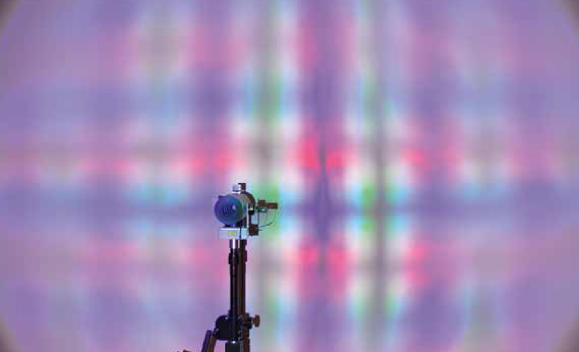
Structure S3 provides a good compromise between color mixing and efficiency. Therefore, it was transferred into a real-world glass light guide (Figure 7). A simple optical test setup similar to the setup of Figure 4 was used to test the color mixing ability of the product. An image of the obtained light distribution was taken for an untreated reference (Figure 8 - top) and for the structured light guide (Figure 8 - bottom). The real-world light distribution fits well with the simulation: a significant mixing is achieved. Yet a darker vertical center line and some neighboring stripes are visible. These are superimposed in a final product by using a higher number of light guide systems. A well-mixed light field with high optical efficiency is the result.
 Figure 7: S3 structure on a complex light guide exit surface
Overall, this example shows that surface micro structures in glass can be tailored to customized systems for obtaining maximum lighting performance.
 and the micro structured surface S3 (bottom)") Figures 8: Photographs taken for an untreated reference (top) and the micro structured surface S3 (bottom)
Figures 8: Photographs taken for an untreated reference (top) and the micro structured surface S3 (bottom)
Summary
The basic working principle of light guides was discussed and important key aspects for material choice and optical design were given. If high light output is demanded, the most suitable material for such kind of optics is glass. It was shown that recent manufacturing methods are able to produce glass light guides with integrated micro structures on an industrial scale.
By means of an example system, the additional benefit of surface structures on the light was illustrated. Optical simulations were performed and compared to a micro structured real-world product - with the very good result that defined scattering and color mixing properties are adjustable and transferable.
Also all kinds of other applications where color mixing is needed are feasible and can be addressed with these new proprietary technologies. For example, LED general lighting systems for in- and outdoor use must provide smooth lighting without any disturbing brightness deviations. Therefore, a lot of these systems currently use a primary glass optics being covered by an additional secondary diffusing polymer sheet. The use of two optical components directly reduces the total optical efficiency due to higher Fresnel losses, while they also need more space, are not easy to clean and increase system costs. Implementation of the diffusion mechanism of the polymer sheet into the primary glass optics provides significant benefits.
Current developments are ongoing to reduce the structure sizes in glass optics even further. This will in particular positively affect light mixing applications, where structured surfaces have to be imaged onto a target area without seeing there sub structures.
References:
[1] Paßlick, C. et al., “Stability of glass versus plastics for transmissive high-power LED optics”, Proc. SPIE 9192, Current Developments in Lens Design and Optical Engineering XV, 919210 (September 25, 2014); doi: 10.1117/12.2061854
[2] Hübner, M. C., “Long Lasting Optics for LED Devices”, LED Professional Symposium + Expo (LpS2014)
