The Influence of LED Emission Characteristics on the Efficiency of Lighting Systems by Osram Opto Semiconductor
In general lighting, efficiency is the main focus. Under specific operation conditions, the main issue appears to be luminous flux. Dr. Roland Schulz, application engineer in the Solid State Lighting division at Osram Opto Semiconductor, takes a deeper look at the influence of LED radiation characteristics.
LED is not always LED. Some luminaire designers had to learn that the hard way. But what makes the difference in an application? Dr. Roland Schulz, application engineer in the Solid State Lighting division at Osram Opto, answers this question and explains the reasons.
As LEDs are becoming more and more widespread for general illumination there is an increasing variety of LED chips and packages. Customers are looking for high efficiency coupled with long life. Designers of lamps and luminaires want the greatest possible freedom to interpret the requirements of customers. It is therefore more important than ever to select the right light source for the particular application. The emission behavior of the LED is a major factor in this respect.
Lamp and luminaire designers get their initial information from the data sheets for the LEDs. These data sheets provide information on the luminous flux and power consumption under different operating conditions. A luminous intensity diagram shows the emission characteristics of the LED at different angles of emission. The half width indicates the emission angle at which the luminous intensity is 50 percent of the maximum value. This information is not sufficient, however, as the basis for selecting an LED because the half width specifies only a single point along the LED emission curve, and the luminous intensity distribution is not an accurate measure of the brightness of the LED in a luminaire.
Influence of Chip Technology on the Emission Characteristics
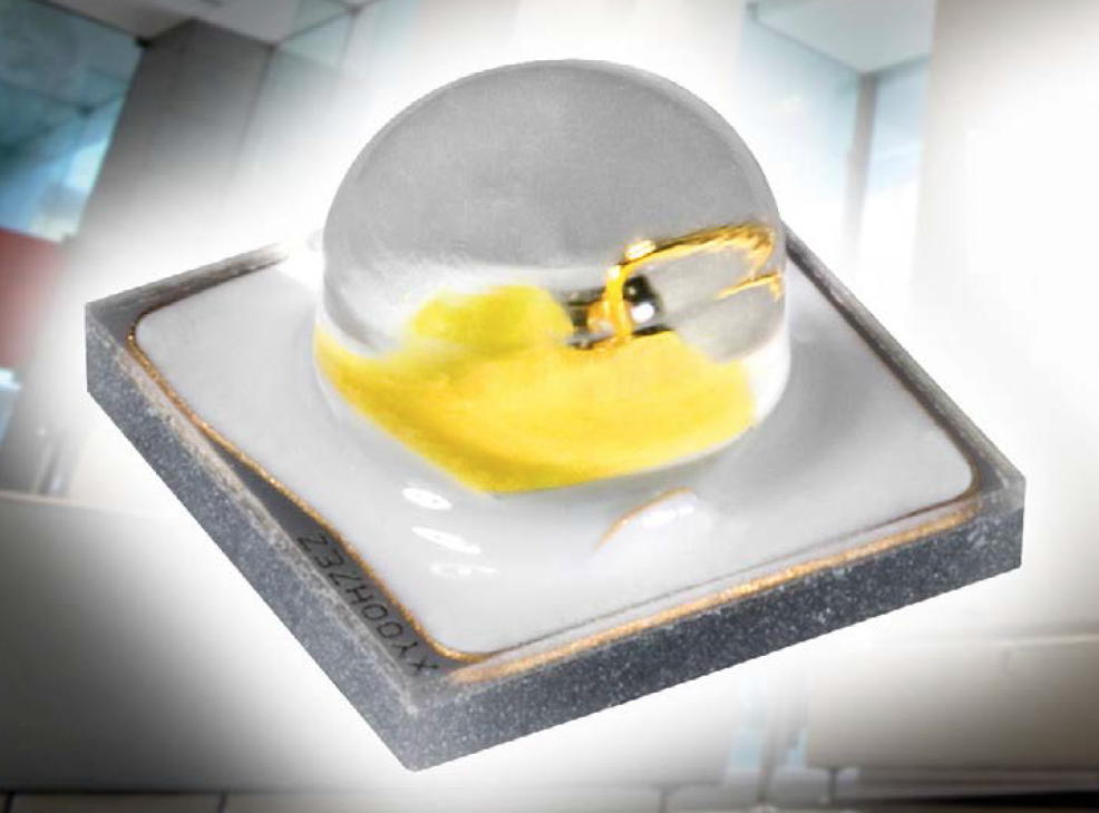
If we take a closer look at the emission characteristics of various LEDs we can certainly find differences that have an impact on the efficiency of a lighting system. A comparison of the luminous intensity diagrams of different LEDs shows that some light sources still have high luminous intensity at an angle of 90 degrees while others emit light only in the forward direction. The reason for this lies to a certain extent in the chip technology. There are two different ways in which LED chips are fabricated (Figure 1). In both cases the light emitting layer, the p-n junction, is grown on a substrate – usually sapphire. If LED chips are manufactured directly from this substrate one gets a volume emitter. The light produced at the p-n junction is emitted in all directions. It is emitted not only to the half-space in front of the LED but also into different angles. External optics, however, can only use the light emitted in the front half-space. The surface emitting LED chip was developed to achieve emission only in the desired direction. A reflector is attached to the light emitting layer and both of these are attached to a new substrate, such as germanium. The original, and thicker, substrate is then removed. The reflector prevents the light produced at the p-n junction from being emitted into the substrate. The result is what is known as a surface emitter that emits light only in the front half-space of the LED with a lambertian emission curve. The maximum possible emission angle here is 90 degrees. What’s more, the conductivity of germanium is better than that of sapphire so the chip remains cooler during operation. Figure 1: Structure of volume emitting and surface emitting LED chips
The differences between volume and surface emitters are even more noticeable when producing white light. White light is generated by using phosphors that convert blue light into longer wavelength spectral colors. In the case of surface emitters the converter material is generally attached as a thin layer (thickness about 50 μm). Even scattering within the layer does not result in significant light emission at angles greater than 90 degrees because the layer is so thin.
On volume emitters the converter material must surround the entire chip, which means that thin layers cannot be used. With typical chip heights of 100 to 150 μm, emission surfaces of 200 μm and more are easily generated, emitting white light over a wide range of angles. For the white-converted chip this results in light emission with a significant intensity at angles greater than 90 degrees.
The Differences in Emission Characteristics
 Figure 2: Emission characteristics for two different LEDs with the same half width of 120°
 Figure 3: Cumulative luminous flux for the two LEDs
The brightness of an LED always relates to the entire luminous flux. In other words, including the light emitted at the side. The emission characteristics of two LEDs with the same half width of 120° may differ significantly (Figures 2 + 3). One LED has lambertian emission characteristics, while the other LED has emission characteristics that deviate from the lambertian curve. Both curves are almost identical at low angles but at more than 60° there are significant differences – despite the same value for the half width. These differences have an effect on the usable luminous flux. The cumulative luminous flux provides the explanation (Figure 4). The cumulative luminous flux is the proportion of the luminous flux that is emitted within a cone with opening angle α. The LED with lambertian emission characteristics emits all its light at angles less than 90°, whereas the LED with emission characteristics that deviate from the lambertian curve emits around 10 percent of its light at an angle greater than 90°, i.e. onto the substrate. At an angle of 60°, this type of LED already offers about 10% lower cumulative luminous flux.
 Figure 4: The luminous flux within a cone with an opening angle of α defines the cumulative luminous flux
Emission Angles above 90° Make it Difficult to Use the Light
Light emitted at angles above 90° hits the board on which the LED is mounted (Figure 5). The light is scattered as a result. If the board is dark with low reflectivity there is a loss of light. This restricts the freedom of the luminaire designer considerably. It will get much more difficult to achieve a dark “off state” for luminaires without reducing their efficiency significantly.
 Figure 5: Mounted LED
There is also the benefit that the light emitted in the half-space in front of the LED can be directed almost anywhere by means of refractive or reflective optics. The light emitted in the half-space in the back of the LED is lost in most applications. TIR optics (TIR = Total Internal Reflection) use the properties of reflectors and lenses to enable compact optics. Normal TIR optics cannot use light emitted at an angle greater than 90° (Figure 6). To ensure total reflection with such LEDs the shape of the lens would have to be modified, particularly on the bottom side. Another option would be to mount such an LED deeper inside of the lens but this results in poorer thermal properties. Both options require a larger size of the lens and will unavoidably lead to higher costs.
 Figure 6: LED with emission >90° with a TIR lens
If LEDs are arranged in clusters, only the light emitted directly upwards is undisturbed (Figure 7). Depending on the spacing between the LEDs the light from one LED will hit its neighboring LED from a certain angle onwards and will be either reflected by the LED or refracted into the LED. LED packages with highly reflective coatings in the package will reduce losses to a minimum (Figure 8). Light emitted at angles above 90° will hit the side of the neighboring LED package, the LEDs solder joint or the board itself. Losses are inevitable here.
 Figure 7: LED cluster with LEDs with an emission angle >90°
In all the above cases the effective brightness of the LED is reduced. Reduced luminous efficacy means that more LEDs are needed and system costs are higher. The price per lumen increases for the luminaire. As a consequence one needs to choose the right LEDs with the most appropriate emission characteristics wisely. It is best to simulate the complete lighting system with the aid of optics design software. As a light source one should use ray files of the LEDs which contain near field information. Thus, the complete ray path of the light can be checked in the first place.
Efficiency in the Luminaire System
Generally speaking, only the light emitted in the half-space in front of the LED can be used. Another possibility of improving the efficiency of a luminaire is to shape the light by the LED itself. This requires special lens geometries for the primary optics of the LED. A spherical lens, as it is commonly used for high power LEDs, hardly changes the intensity distribution of an LED at all. By using aspherical lenses, in other words, ones that deviate in some way from the pure spherical shape, almost any intensity distribution or half width angle of emission can be achieved (Figure 9). Good examples are the different Oslon SSL LEDs that are available with emission angles of 80° and 150°. The Oslon SSL 80 has a lens that is higher than a sphere of the same diameter. This lens has a higher power than a corresponding spherical lens of the same diameter, so the angle of emission is smaller. The Oslon SSL 150, on the other hand, has a flatter lens than a corresponding sphere so the angle of emission is wider. Narrow or wide angles of emission have different benefits depending on the application. A narrow angle – such as that of the Oslon SSL 80 – is ideal for the use of lenses as secondary optics because more light hits the lens and the light can be better shaped. A wide angle – such as that of the Oslon SSL150 – is suitable for reflectors. The cumulative luminous flux increases slowly, the luminous flux at wide angles is very high. The light can therefore be shaped very efficiently, even if flat reflectors are used. If the overall system has a low profile, surfaces can be uniformly illuminated by keeping a narrow system height. This effect is used in panel lights and simple downlights.
 Figure 8: LEDs with highly reflective packages help minimize losses
 Figure 9: Different emission profiles of Oslon SSL 80, Oslon SSL 150 and Oslon Square compared with lambertian emission
The emission profile of the Oslon Square LED deviates from the lambertian emission characteristic but the half width corresponds to that of many LEDs and is 120°. Within the half width the luminous intensity is greater than that of a lambertian emitter, and smaller outside the half width. This means that the best possible use can be made of the available luminous flux in the particular application.
The LED chips in all the Osram high-power LEDs are mounted in a highly reflective package. All light is turned into useful, be it the margin of light scattered to the back or the light coupled into the LED from cluster applications. It is therefore not lost for the application.
Summary
Data tables for LEDs are useful in providing an overview of their properties but they are not sufficient for designing a complete lighting system that has to operate at maximum efficiency in terms of power consumption and operating costs. The emission behavior of the LEDs also needs to be known in detail and checked against the requirements of the application. The recommended way to prove the performance of the LEDs inside the luminaire is to simulate the complete system with an optics design software and ray files of the used light sources. OSRAM offers measured ray data for all LEDs and all standard programs. By considering all this, disappointments when building up first samples of a luminaire will be a thing of the past.
Definitions:
Emission characteristics: Radiant power per solid angle as a function of the direction of emission; the solid angle is defined as the surface projected onto a sphere, divided by the square of the radius of this sphere.
Half width: Angle of emission at which the luminous intensity has fallen to 50 percent of the maximum luminous intensity.
Cumulative luminous flux: Cumulative light output of a light source that is emitted in a cone with an opening angle α.
