Thermal Transient Testing of LEDs for More Reliable SSL Products by Mentor Graphics
An LED device’s reliability, useful operating lifetime and luminous flux are basically determined by the junction temperature; therefore, so is the lifetime and reliability of the final SSL application. Thermal transient testing is now supported by new industrial laboratory testing standards published by JEDEC. Dr. Andras Poppe, Mechanical Analysis Division, MicReD, at Mentor Graphics will explain the corner stones of this standard and discuss application examples. This includes measurement of the RthJC, test-based thermal modeling of the LED package, hot lumens prediction, and monitoring of degradation of the thermal interfaces during life-time test, to name just a few.
An LED device’s reliability, useful operating lifetime and luminous flux are basically determined by the junction temperature; therefore, so is the lifetime and reliability of the final SSL application (such as street lighting luminaires, cars’ headlights, etc.). And this temperature is directly proportional to the total junction-to-ambient thermal resistance of the heat-flow path of the LED application.
Key contributors are the interfacial thermal resistance between the different sections of the heat-path such as thermal resistance of the die-attach, thermal resistances of solder/ glue layers, and the thermal resistance of the TIM applied between the LED component and luminaire heat-sink (Figure 1). Thermal transient measurements completed with subsequent structure function analysis [1] has been proven to be a powerful means to test, monitor, and model these resistances during quality assurance, reliability testing, and thermal modeling for the design of system-level thermal management solutions.
 Figure 1: Thermal interfaces in the junction-to-ambient heat-flow path of a typical power LED application
In the case of power semiconductor devices packages and LEDs, the thermal transient testing is now supported by new industrial laboratory testing standards published by JEDEC, such as JEDEC standard JESD 51-14 aimed at the measurement of the RthJC junction-to-case thermal resistance and the JEDEC JESD 51-5x series of standards aimed at the correct measurement of LEDs’ real thermal resistance or thermal impedance with consideration of the emitted optical power (total radiant flux) of the device under test.
Given examples of the thermal transient testing for characterizing LED applications include measurement of the RthJC combined with test-based thermal modeling of the LED package aimed at CFD based luminaire-level thermal simulations and hot lumens prediction, monitoring of degradation of the thermal interfaces during life-time test or reliability tests, and last but not least, the application of the thermal transient testing in qualifying the thermal quality of the die-attach layers.
Figure 2 presents the basic concept of thermal transient testing of LEDs. The test equipment forces a stepwise change in the heating power of the LED under test and measures the transient response of its junction temperature. Normalized by the change in the heating power this curve is called the Zth(t) thermal impedance curve. After post processing, the thermal impedance is turned into alternate formats that can be used to represent the thermal behavior or thermal properties of the LED’s junction-to-ambient heat-flow path for a particular purpose. For example, the complex locus is a format best suited to describe the thermal impedance of AC-driven LEDs; the pulsed thermal resistance diagrams are well suited to describe how LEDs would thermally react when dimmed with a pulse-width modulation; structure functions provide non-destructive means of failure analysis; and even a dynamic compact thermal model can be created to represent the LED package during a luminaire level CFD-based thermal simulation.
 Figure 2: Overview of thermal transient testing of LEDs: the junction temperature response to a stepwise change in the LED’s heating power is measured and is post processed
New JEDEC Standards Support Thermal Testing of LEDs
LEDs’ operation extends to multiple domains: electrical, thermal, and optical, with rather strong mutual dependence among the major characteristic quantities such as forward current, forward voltage, total light output (e.g., total radiant flux), heat generated within the device, and the junction temperature (Figure 2). Therefore, testing of power LEDs, including thermal characterization, is not straightforward.
As measurement of light emission of LEDs and LED-based products is affected by the junction temperature, CIE (International Commission on Illumination) have also revised their recommendations on LED measurements and established several technical committees (such as CIE TC2-64, TC2-64 or TC2-76) that aim to define LED testing procedures with consideration of LED operating junction temperature. Thermal testing of LED components, or small LED assemblies, falls within the general category of thermal testing of packaged semiconductor devices – therefore the JC15 committee of JEDEC (Joint Electron Devices Engineering Council), dealing with thermal characterization of packaged semiconductor devices initiated a series of white papers on the need for LED thermal testing standards [2].
In the case of power semiconductor devices packages and LEDs, thermal transient testing is now supported by new industrial laboratory testing standards published by JEDEC, such as JEDEC standard JESD 51-14 [3] aimed at the measurement of the RthJC junction-to-case thermal resistance [3], and the JEDEC JESD 51-5x series of standards [5-9] aimed at the correct measurement of LEDs’ real thermal resistance or thermal impedance with consideration of the emitted optical power (total radiant flux) of the device under test. When the generic method of the JEDEC JESD 51-14 compliant measurement is combined with the JEDEC JESD 51-5x series of LED thermal testing standards, the real value of RthJC junction-to-case thermal resistance can be obtained. In most of the LED packages, the assumption of a single heat-flow path from the LED’s junction towards the cooling surface of the LED package (Figure 3) is valid.
 Figure 3: A classical power LED package soldered to a metal core PCB substrate with its exposed cooling surface (the package ‘case’ surface)
Measurement of the Real Thermal Resistance of LEDs and LED Assemblies
As mentioned before, measurement of the emitted optical power is important when calculating the LEDs’ real thermal resistance (or thermal impedance if the dynamic thermal behavior is of interest). By neglecting the emitted optical power in this calculation, the resulting thermal resistance/impedance value would be smaller, and providing such thermal metrics on LED data sheets can easily mislead customers and may result in improper design of the thermal management of the final LED application. This was the main motivation of the JEDEC JC15 committee when the work toward the definition of LED thermal testing standards started in 2008.
Four documents (JESD 51-50 through 53) were created to be widely used in thermal characterization of packaged semiconductor devices and are specific to LEDs.
Transient Technique to Measure LEDs’ Junction-to- Case Thermal Resistance
From a thermal point of view, packaged LEDs are similar to any other power semiconductor device for which the most important thermal metric is their junction-to-case thermal resistance. For the accurate and repeatable measurement of this metric, the JEDEC JC15 committee has developed a new JESD51-14 testing standard [3] based on the so-called transient dual interface method.
This method is characterized as follows:
During the measurement, we assume that there is a single heat conduction path from the junction (location of heating) toward the ambient through an exposed cooling surface of the package. This surface is called the package ‘case’ (Figure 3). A further assumption is that such packages are designed to be heat-sunk during normal operation. In figure 3, the MCPCB substrate acts as a primary heat spreader and heat sink; and in a final application environment, it must be mounted to a cooling assembly. Thus, during a JESD 51-14 compliant RthJC measurement, the device under test has to be attached to a cold plate.
According to this standard, the junction temperature cooling transients of the device need to be recorded twice, using the JESD 51-1 electrical test method [10], with two different qualities of the thermal interface between the package ‘case’ surface and the cold plate. In one measurement, good thermal contact between the package ‘case’ and the cold plate need to be established (typically by applying any thermal interface material between the mating surfaces). This is also known as ‘wet’ condition because using simple silicon oil wetting the interface is sufficient. In the other measurement, bad thermal contact between the package and the test environment is needed; that is, no thermal interface material shall be used during this measurement. This condition is also known as ‘dry’ condition because no wetting material like silicon oil or thermal grease is used. In other words, once a thermal interface material (TIM) is applied, in the other case, no TIM is applied. Figure 4 shows test setup schematics.
The effect of the two different qualities of the ‘case’ – ‘cold plate’ thermal interface on the two measured thermal impedance curves – is that at a characteristic time the curves start diverging. The Rth value corresponding to this divergence point is the transient junction-to-case thermal resistance. The JESD 51-14 standard provides two methods to find the ‘exact’ value of the transient RthJC value in a repeatable and reproducible way. One method is based on the difference between the structure functions (Figure 4).
 Figure 4: Identification of the package RthJC thermal resistance of a power LED device with the transient dual interface method of JESD 51-14 and the dynamic compact thermal modeling of the main heat-flow path of the package
Note: Structure functions are the thermal capacitance – thermal resistance maps of the junction-to-ambient heat-flow path; the shape of the structure function depends on the thermal properties and the geometry of the subsequent sections of the heat-flow path. For details on structure functions see the original paper of V. Székely or consult Annex A of the JESD 51-14 standard [3] or see Sections 4.4.4 and 4.4.5 of [11].
The JESD 51-14 standard provides definitions of the procedure used to find this separation point in a repeatable way. According to the standard, e.g., if the difference between the structure functions is greater than a pre-defined ε value, the divergence point is found. (The second method defined in the standard is based on the difference of the first derivatives of the measured thermal impedance curves – the divergence point and the corresponding RthJC value is found in a similar way as in the case of the structure-function based method.) This separation point determines the value of RthJC.
If the emitted optical power was considered in the calculation of the heating power of the LED during these tests (as the JESD 51-5x standards [5-9] require), the identified RthJC value will be the real, physical value of the junction-to-case thermal resistance of the given LED package. This value is not only the major thermal characteristic of the LED package to be published on data sheets, but it can also be used in compact modeling of the LED component aimed at system level thermal simulations of LED based luminaires.
For details of different aspects of the JESD 51-14 compliant RthJC measurements see the original papers by D. Schweitzer et al [12-16]. The first report about using this test method for the measurement of LEDs was published by S. Müller et al [17].
Test-Based Dynamic Compact Modeling of LED Packages
As suggested in the previous section, the junction-to-case thermal resistance of LED packages is also suitable for compact modeling of LED packages. In principle, LED packages are well-modeled by a so-called JEDEC 2R model. In the case of LEDs, the two elements of this 2R model are the junction-case thermal resistance (corresponding to the junction-to-bottom resistance of the JEDEC 2R model) and the junction-to-lens thermal resistance (representing the junction-to-top part of the JEDEC 2R model) (Figure 5).
 Figure 5: The dynamic extension of the JEDEC 2R compact model for LED applications
As described, measurement of the (real) RthJC value of LED components is possible based on standards, but the identification of the junction-to-lens resistance raises problems: in practice it can hardly be measured. Because most of the heat dissipated at the LEDs’ junctions leaves toward the cooling assembly of the LED packages, the junction-to-lens thermal resistance is large. Thus, as a first approximation, it can be neglected. However, if the need for accuracy in creating LED package compact models is required, this value can be determined by CFD simulation of the LED application.
There are situations when a steady-state compact model is not sufficient, such as for the AC-driven LEDs or the study of thermal effect of PWM-based dimming. In these cases, the dynamic extension of the JEDEC 2R model can be used (Figure 5). The element values of (thermal capacitance and thermal resistance values) can be obtained in a straightforward manner, e.g., by a step-wise approximation of the structure function up to the RthJC value, representing the thermal impedance of the LED package.
Such an approximation is shown in figure 4. The sum of the thermal resistances of the model is equal to the RthJC value. The model is independent of the applied boundary conditions at the case surface of the package, so such a model can be considered as a BCI (boundary condition independent) compact model. A complete dynamic LED package compact thermal model is shown in the right hand side of figure 5. Like the classical JEDEC 2R model, this dynamic extension of the JEDEC 2R model is also a test-based compact model.
The step-wise approximation of the structure function (Figure 4) is a natural extension of the data processing part of the JEDEC JESD 51-14 compliant transient RthJC measurement method as implemented the T3Ster® Master data processing software which is also equipped with an interface which propagates such test based dynamic compact models towards CFD-based thermal simulation tools.
When the thermal transient measurement is combined with radiometric/photometric measurements of LEDs, JEDEC JESD 51-51/51-52 compliant measurement of LEDs’ properties is possible. Synchronized with the powering of the LED under test, the integrating sphere based radiometric/photometric test setup provides the light output characteristics of the LED under test. By sweeping the temperature of its temperature-controlled LED fixture, parameters of a multi-domain LED model (including temperature dependence of the luminous flux) can be automatically identified. The workflow is shown in figure 6.
 Figure 6: Typical work-flow for component level measurement, modeling, and luminaire level CFD simulation
CFD simulation tools are typically used in the design of complete LED luminaries. Application of compact thermal models of (LED) packages allows speeding up the CFD simulation so that different design scenarios of LED luminaires can be analyzed and LED junction temperatures accurately calculated.
As during the JEDEC JESD51-51 tests used to obtain the thermal impedance curves for the identification of the real RthJC values of LED packages and the light output properties are also measured, it is possible to measure the junction temperature dependence of these properties as well.
Besides the total radiant flux (needed for the thermal measurements), the same measuring setup can also deliver the total luminous flux, also as function of junction temperature, thus, the temperature sensitivity of the luminous flux can be easily identified for a constant DC current driven LED. In the simplest case, this temperature dependence can be approximated by a linear relationship allowing hot lumen predictions of LEDs as part of the CFD analysis of an LED luminaire.
The equations used in the multi-domain LED model implemented in the FloEFD tool are the following:

where VF0, Фe0 and ФV0 are reference values of the forward voltage, radiant flux (emitted optical power) and luminous flux, respectively (measured at the T0 reference temperature of the LED’s junction) and SVF0, SФe0 and SФV0 describe the temperature dependence of the quantities.
Equations (1) and (2) are used during the CFD simulation to update an LED’s heating power and equation (3) is used to calculate the hot lumens of an LED for the TJ junction temperature obtained by the CFD simulation.
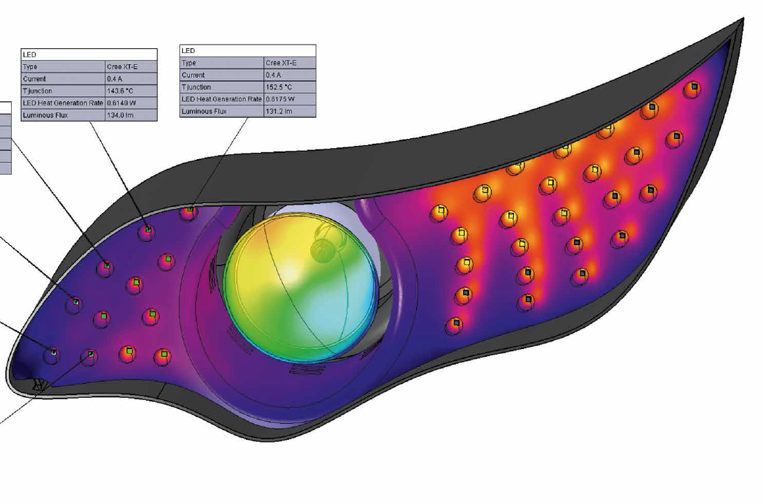
Luminaire-level CFD simulations are especially useful in the case of LED-based luminaires with very complex geometry where measurements on actual product prototypes under different conditions is difficult. In applications where luminous output is critical even under harsh environmental conditions, such as automotive luminaire, the hot lumen calculation realized within a CAD based CFD tool is crucial (Figure 7).
 Figure 7: CFD simulation results of a head-light luminaire completed with LEDs for running daylight using the CAD model of the luminaire as input for the CFD simulation. Results include temperature map and calculated hot lumens of each LED of the luminaire
Example of Thermal Transient Testing in Failure Analysis of LEDs
In an independent series of tests carried out by the joint team of the University of Pannonia (Veszprém, Hungary) and the Budapest University of Technology and Economics (Budapest, Hungary), it was shown that the light output degradation of LEDs measured during LM-80 compliant aging is strongly correlated with degradation of the quality of the junction-to-ambient heat-flow path of the LED product tested [18] (Figure 8). The observed changes included delamination of the attachment of the LED package to the substrate (MCPCB in this case), as well as degradation of the thermal conductivity of the thermal interface material used in the test setup. The corresponding increases in the interfacial thermal resistances are indicated by the elongation of flat regions of structure functions.
As Figure 8 shows, the delamination of the attachment layer occurred within 500 h of aging time (see the differences between the 0 h and 500 h plots). TIM aging occurred between 500 h and 2,000 h of aging time. After 2,000 h of aging, no further degradation of the quality of the junction-to-ambient heat-flow path was observed.
") Figure 8: Thermal interface degradation indicated by structure functions during an LM-80 life-time test experiment [18] (image courtesy the Budapest University of Technology and Economics)
Figure 8: Thermal interface degradation indicated by structure functions during an LM-80 life-time test experiment [18] (image courtesy the Budapest University of Technology and Economics)
In this LM-80 compliant aging test of LEDs, thermal transient measurements proved to be an effective means of post-stress failure analysis tools. The idea that thermal transient measurement of LEDs is a good means of pre-stress and post-stress test in reliability analysis is exploited recently in the EU funded research project NANOTHERM [19]: a thermal reliability testing system is being developed in the project in which thermal transient testing will be used as pre- and post-stress analysis technique. This concept applied to LEDs has been recently published [20].
In another example, die-attach quality issues were detected. The diagrams in figure 9 show the results of thermal transient testing of 15 randomly selected samples of a recent high-end power LED purchased from a distributor of a well-recognized LED vendor.
In figure 9a, the measured thermal impedance, for two samples out of the lot of 15, is already significantly higher 10 min. after turning the power on. This time range is characteristic to the die-attach region. The conclusion that the increased overall steady-state thermal resistance of these two samples was caused by the increased die-attach thermal resistance is confirmed as the structure function shown in figure 9b.
The fact that die-attach issues have been found in about 13% of the LEDs purchased through usual commercial channels highlights the importance of testing the die-attach quality during production.
Such in-line testing of die-attach quality LEDs raises a number of questions:
First of all, to meet the speed requirements of the production lines, complete steady-state to steady-state thermal transient measurements are not feasible. In our earlier studies [21, 22], it was shown that transient response to short (typically 10 min.) heating pulses already carry the necessary information about the die-attach quality; thus, test waveforms with an overall length of 80 to 200 min. are appropriate, depending on the actual thermal time-constant of the LED product to be tested. Such a time frame corresponds to the throughput of production lines.
Another important issue is that during in-line testing of LEDs, there is no possibility to find the temperature sensitivity of the forward voltage of the LEDs, as would be required by the standard laboratory testing of thermal properties.
This problem can be solved by matching the initial part of the measured ΔVF(t) transients to the real Zth(t) curves in the initial section (in the 1..10 min. range) where the heat-wave generated by the short heating pulse propagated only in the LED chip itself and is not yet influenced by the quality of the die attach. A recent paper by T. Dannerbauer and T. Zahner [23] provides details on this. The key in such a testing solution is the accurate measurement of the early part of the forward voltage transient.
 Measured thermal impedances, b) corresponding structure functions. The results for the two samples showing increased die attach thermal resistance are shown with thick lines") Figure 9: Thermal transient measurement results of 15 randomly selected commercial samples of recent SMD packaged high power white LEDs: a) Measured thermal impedances, b) corresponding structure functions. The results for the two samples showing increased die attach thermal resistance are shown with thick lines
Figure 9: Thermal transient measurement results of 15 randomly selected commercial samples of recent SMD packaged high power white LEDs: a) Measured thermal impedances, b) corresponding structure functions. The results for the two samples showing increased die attach thermal resistance are shown with thick lines
Conclusions
Thermal transient testing of LEDs is a powerful tool in thermal characterization of LED products in different phases of design and production.
Classical laboratory measurements of LEDs based on thermal transient testing can deliver accurate and repeatable results for the real junction-to-case thermal resistance of LED packages. A small addition to the data processing of the JEDEC JESD 51-14 compliant measurement of the junction-to-case thermal resistance measurements results in test based dynamic compact thermal models, which allows fast system CFD simulations of LED-based lighting solutions.
The other major application of thermal transient measurements of LEDs is in the reliability testing and quality assurance of LEDs. Used as a pre- and post-stress testing method, such measurements provide a good means of failure analysis. When implemented in production lines, thermal transient testing can be used for die-attach quality testing. All these applications contribute to the design and manufacturing of more reliable LED-based products.
References:
[1] V. Székely, T.V. Bien , “Fine structure of heat flow path in semiconductor devices: a measurement and identification method”, Solid-State Electronics 31(9):1363-1368 (1988)
[2] A. Poppe, C. J. M. Lasance, “On the Standardization of Thermal Characterization of LEDs”, LED PROFESSIONAL REVIEW 2009:(13) pp. 22-29. (2009)
[3] JEDEC Standard JESD51-14 “Transient Dual Interface Test Method for the Measurement of the Thermal Resistance Junction-To-Case of Semiconductor Devices with Heat Flow Through a Single Path”, (November 2010)
[4] D. Schweitzer, “Transient dual interface measurement of the Rth-JC of power semiconductor packages” ELECTRONICS COOLING 16:(9) (2010)
[5] JEDEC Standard JESD51-50, “Overview of Methodologies for the Thermal Measurement of Single- and Multi-Chip, Single- and Multi-PN Junction Light-Emitting Diodes (LEDs)”, (April 2012)
[6] JEDEC Standard JESD51-51, “Implementation of the Electrical Test Method for the Measurement of the Real Thermal Resistance and Impedance of Light-emitting Diodes with Exposed Cooling Surface”, (April 2012)
[7] JEDEC Standard JESD51-52, “Guidelines for Combining CIE 127-2007 Total Flux Measurements with Thermal Measurements of LEDs with Exposed Cooling Surface”, (April 2012)
[8] JEDEC Standard JESD51-53 “Terms, Definitions and Units Glossary for LED Thermal Testing”, (May 2012)
[9] A. Poppe, C. J. M. Lasance, “Standardization of LED thermal characterization”, In: C. J. M. Lasance, A. Poppe (eds.) Thermal Management for LED Applications, Springer, (2013). pp. 197-264. (Solid State Lighting Technology and Application Series) DOI 10.1007/978-1-4614-5091-7
[10] JEDEC Standard JESD51-1, “Integrated Circuits Thermal Measurement Method – Electrical Test Method (Single Semiconductor Device)”, (December 1995)
[11] G. Farkas, A. Poppe, “Thermal testing of LEDs”, In: C. J. M. Lasance, A. Poppe (eds.), Thermal Management for LED Applications, Springer, (2013). pp. 73-165. (Solid State Lighting Technology and Application Series) ISBN: 978-1-4614- 5090-0, DOI 10.1007/978-1-4614-5091-7
[12] D. Schweitzer, H. Pape, L. Chen, R. Kutscherauer, M. Walder, “Transient dual interface measurement – A new JEDEC standard for the measurement of the junction-to-case thermal resistance”, In: Proceedings of the 27th IEEE Semiconductor Thermal Measurement and Management Symposium (SEMI-THERM’11), 20-24 March 2011, San Jose, USA, pp. 222-229
[13] H. Pape, D. Schweitzer, L. Chen, R. Kutscherauer, M. Walder, “Development of a standard for transient measurement of junction-to-case thermal re-sistance”, In: Proceedings of the 12th International Conference on Thermal, Mechanical and Multi- Physics Simulation and Experiments in Microelec-tronics and Microsystems (EuroSimE’11), 2011, pp. 1/8 - 8/8
[14] D. Schweitzer, H. Pape, and L. Chen, “Transient Measurement of the Junction-to-Case Thermal Resistance Using Structure Functions: Chances and Limits”, In: Proceedings of the 24th IEEE Semiconductor Thermal Measure-ment and Management Symposium (SEMI-THERM’08), 16-20 March 2008, San Jose, USA, pp. 193-199
[15] D. Schweitzer, “Transient Dual Interface Measurement of the Rth-JC of Power Packages”, In: Proceedings of the 14th International Workshop on THERMal INvestigation of ICs and Systems (THERMINIC’08), 24-26 Sep-tember 2008, Rome, Italy, pp. 14-19
[16] D. Schweitzer, H. Pape, R. Kutscherauer, M. Walder, “How to Evaluate Transient Dual Interface Measurements of the Rth-JC of Power Packages”, In: Proceedings of the 25th IEEE Semiconductor Thermal Measurement and Management Symposium (SEMI-THERM’09), 15-19 March 2009, San Jose, USA, pp. 172-179
[17] S. Müller, T. Zahner, F. Singer, G. Schrag, G. Wachutka, “Evaluation of Thermal Transient Characterization Methodologies for HighüPower LED Applications”, In: Proceedings of the 17th International Workshop on THERMal INvestigations of ICs and Systems (THERMINIC’11), 27-29 Sep-tember 2011, Paris, France, pp. 104-109
[18] A. Poppe, G. Molnár, P. Csuti, F. Szabó, J. Schanda, “Ageing of LEDs: A Comprehensive Study Based on the LM80 Standard and Thermal Transient Measurements”, In: CIE 27th Session-Proceedings, CIE 197:2011: (Vol-ume 1), 10-15 July 2011, Sun City, South Africa, pp. 467-477
[19] www.project-nanotherm.com
[20 S. Noijen, S. Fritzsche, A. Steffen Klein, A.Poppe, G. Kums, O. van der Sluis, “Integrating Advanced Interconnect Technologies in a High Power Lighting Application: First Steps”, In: Proceedings of the 19th International Workshop on THERMal INvestigation of ICs and Systems (THERMINIC’13), 25-27 September 2013, Berlin, Germany, pp. 276-280
[21] P. Szabó, A. Poppe, M. Rencz, “Studies on the possibilities of in-line die at-tach characterization of semiconductor devices”, In: Proceedings of the 9th Electronics Packaging Technology Conference (EPTC’07), 10-12 December 2007, Singapore, pp. 779-784
[22] P. Szabó, M. Rencz, G. Farkas, A. Poppe, “Short time die attach characteri-zation of LEDs for in-line testing application”, In: Proceedings of the 8th Electronics Packaging Technology Conference (EPTC’06): Volume One. Singapore, 6-8 December 2008, pp. 360-366
[23] T. Dannerbauer, T. Zahner, “Inline Rth Control: Fast Thermal Transient Evaluation for High Power LEDs”, In: Proceedings of the 19th International Workshop on THERMal INvestigation of ICs and Systems (THERMINIC’13), 25-27 September 2013, Berlin, Germany, pp. 172-175
