Using Integrating Spheres Correctly to Measure LEDs
LEDs have opened up new dimensions of design freedom, allowing architects and designers to give free rein to their creativity. Light-emitting diodes permit manifold design solutions as a light source in illumination products. However, a suitable measuring method for comparing key technical data is required in order to get the best out of the diversity of illumination products available. Mikolaj Przybyla from GL OPTIC, a Just Normlicht GmbH division, explains crucial product requirements and what to take care about when calibrating a measurement system.
A generally reliable and suitable measurement method for a wide range of lighting products is to measure the luminous flux and radiant power with an integrating sphere. A high-resolution spectrum analyzer can be used to measure transmission and emission spectra, but the so-called integrating sphere can determine the radiant power or luminous flux of light sources. Therefore the integrating sphere, also known as the Ulbricht sphere after its inventor, is among the most important instruments used in spectrometer applications (Figure 1).
 Figure 1: Typical measurement setup with a large integrating sphere calibrated with a laboratory grade spectrometer
German engineer Richard Ulbricht was commissioned to construct a three-phase power station for the train stations in the city of Dresden. In connection to this, he also became involved with the illumination of the stations. For his photometric investigations Ulbricht utilized the multiple reflections produced by light, and it was in the course of this work that he developed the integrating sphere. Essentially, the integrating sphere is a hollow sphere whose inner surface is coated with a diffuse reflecting material and is completely opaque and closed on all sides. The radiation is fully integrated and mixed inside the integrating sphere before being decoupled for measurement by a detector. In practice the test object is secured at the center of the sphere so that the luminous flux can be quantified in all directions. The overall energy emitted by a source can thus be determined regardless of the source’s structure or the spatial distribution of the emission. With this method it is possible to obtain reliable results for many different types of light source and to take all designs, illumination angles and types into account. Integrating spheres are used successfully for measuring incandescent and electroluminescent light sources. They are also suitable for characterizing light sources comprised of LEDs or OLEDs.
The Right Detector – Photometer or Spectrometer
An integrating sphere is just one part of the overall measuring system – a detector is also required to quantify the intensity of the signal. The detector is a measuring device that is connected to the sphere. An integrating sphere and photometer were typically used to measure conventional incandescent light sources that emit a continuous spectrum across a broad spectral range. With the help of photometry it is possible to determine the energy-efficiency classes and average service life of lamps as well as the spatial distribution of light. A photometer mounted to the inner wall measures the light level inside the sphere. This device frequently comes with an optical correction filter (V, λ) that adapts the sensitivity of the device to the characteristic sensitivity of the human eye. Measuring the integrated radiation accordingly provides a basis for assessing how the light source will be perceived by the human eye.
For the measurement of LEDs and other light sources that emit a non-continuous spectrum, a spectral measurement device must be used. While photometric measurement systems specify parameters in lux, candela, cd/m. or lumen, spectroradiometric measuring equipment is capable of indicating additional parameters such as the dominant wavelengths, peak wavelengths, bandwidth, CCT (color temperature), and CRI (color rendering index). Spectral measurements achieve very accurate results because they quantify the spectral power distribution of a light source. Luminous flux is measured by a spectrometer in conjunction with a diffuser and a suitable cosine corrected head. The spectrometer is connected to the integrating sphere and it measures the integrated signal level in lumen [lm]. The application software installed then calculates the photometric and colorimetric values that cannot be ascertained with a traditional photodetector. The basis for the measurement data continues to be the energy emitted by a source. This measurement method also eliminates the errors that can result when a detector incorrectly renders the sensitivity of the human eye across different wavelengths.
This aspect is especially important for LED measurements, as these sources emit light in a limited wavelength range that contains sharp and narrow peaks. In this case, the detector is influenced by different illuminants, with high energy in several wavelength ranges and lower or near-zero signal strengths in other ranges. LEDs have a somewhat gaseous spectral distribution pattern with a specific peak wavelength and a halfwidth of fewer than ten nanometers. Blue, red and white LEDs, in particular, are affected by pronounced deviations in luminous intensity and the dominant wavelength due to the relatively poor adaptation of the filters to the defined flanks of the V(l) function. For example, error rates of several hundred percent are not uncommon for blue LEDs. In the case of white LEDs, on the other hand, correct evaluation of the blue peaks is extremely important for the accuracy of the color coordinates. Another problem is that different photometers deliver different results depending on the respective filter parameters and optical correction (V, λ). A precision spectroradiometer avoids this pitfall because a computer-based analysis of the spectrum (Figure 2) uses precisely defined functions in accordance with the CIE 127:2007 standard issued by the International Commission on Illumination (CIE). Spectroradiometers are therefore the recommended choice for measuring LED light sources.
, Color coordinates and correlated color temperature. Additionally radiometric value of radiant power [mW] is calculated")
Figure 2: Typical measurement plot of a cold white LED, with the required figures: Lumen output, rendering indices R1 - R15 and Ra (CRI), Color coordinates and correlated color temperature. Additionally radiometric value of radiant power [mW] is calculated

The Appropriate Sphere
The inside of an integrating sphere is coated with a special material designed to diffuse the reflected light. Barium sulfate (BaSO4) is often used for this application. Optical PTFE (polytetrafluoroethylene) offers ideal reflection characteristics across a broad wavelength range, and a gold coating is applied for infrared radiation values in excess of 700 nm. The coating used in older spheres had a light reflection coefficient of 80%, which produced good results in conjunction with the detectors of previous generations. A spectrometer allows materials with a light reflection coefficient of 97% to be used. This enables better integration and higher signal strength at the detector entry point, and it makes the measurement results much more accurate.
An important CIE requirement is to consider the self-absorption. The methods used should be able to determine which part of the signal emitted by a specific source is also absorbed by this source. The absorption can be due to the housing or to all the elements within a sphere that are used to install a sample. The CIE requirement can be met by installing an auxiliary source in the sphere to measure the absorption of the tested light source. This is then factored into the final measurement results.
It is important to choose an appropriate sphere diameter when designing a measurement setup (Figure 3). Specific requirements prohibit the maximum physical size of a light source from exceeding 10% of the inner diameter of a sphere. Until recently, this meant that a sphere with a diameter of at least 1 meter had to be used to measure a source spanning 10 cm in diameter. Accordingly, a 4-meter sphere was required to measure objects of 40 cm in size, and so on. By compensating for self-absorption, it is now possible to measure light sources twice as large without compromising measurement accuracy. The results also depend on the shape of the source. In a sphere with a diameter of 500 mm, objects measuring up to 16 cm x 16 cm can be measured. A sphere with a diameter of 2,000 mm can therefore be used to measure sources of up to 60 cm x 60 cm in size. In the case of fluorescent lamps, the length of the source can have a diameter that is almost as wide as the sphere itself.
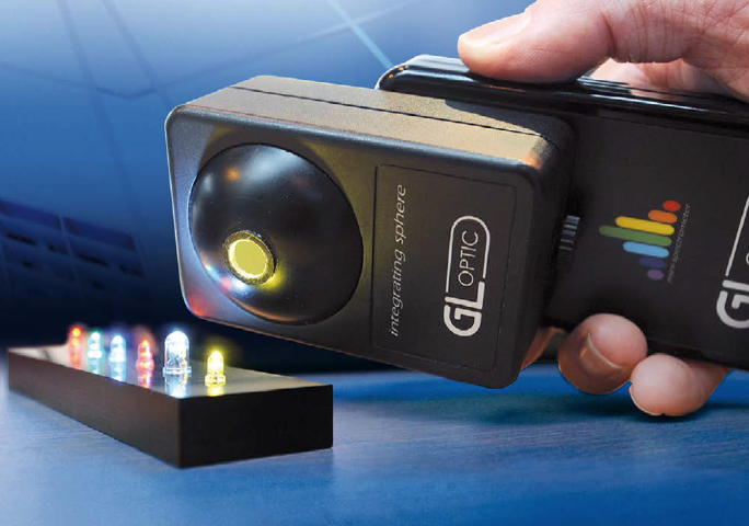
 Figure 3: Small integrating spheres are also used in high quality handheld instruments for single LED measurements
Calibrated Measurement Setup
To guarantee the desired level of reliability, the instrumentation used must be calibrated. Every measurement system comprising an integrated sphere and a spectrometer requirescalibration. The calibration source is a reference lamp with known spectral distribution and luminous flux values. These light sources are calibrated by certified laboratories that use an ideal black body radiator and a monochromator as a reference for determining the spectral distribution and luminous flux of a reference lamp. The manufacturer normally calibrates measurement setups, which should be repeated every 12 months.
Spectrometers are calibrated in three steps:
• Wavelength calibration
• Spectral calibration
• Absolute calibration
Since the blue spectral component in halogen lamps accounts for only about 10% of the energy available along an 800 nm wavelength, it is frequently recommended that a corresponding LED be used for absolute calibration when measuring white LEDs with a pronounced blue component in their light. This should avoid calibration errors that can occur in conjunction with the scattered light of a white LED.
However, this is not required for devices that feature optical stray light reduction (OSR) that are used in high quality spectroradiometers. Applying suitable filters and mathematical models reliably prevents calibration errors caused by stray light.
Summary
The combination of longevity and extremely robust internals as well as the high light output expected of LEDs makes this illumination technology truly unique. It therefore comes as no surprise that the requirements for a color consistency are very high when LEDs are being binned into the color groups. Adding to this is the increasing need to optically characterize LEDs, since their illumination characteristics are critical to safeguarding compliant product quality. Integrating spheres have proven to be versatile and effective measuring tools and are even essential for some applications.
References:
[1] CIE Technical Report CIE127-2007 Measurement of LEDs, ISBN 978 3 901 906 58 9
[2] Zong Y., Uncertainty analysis of stray – light correction, 2010 CIE Expert Symposium, Bern, Switzerland
