Integrating chamber cone light using LED sources
A system to provide radiant energy of selectable spectral characteristic (e.g. a selectable color combination) uses an integrating cavity to combine energy of different wavelengths from different sources. The cavity has a diffusely reflective interior surface and an aperture for allowing emission of combined radiant energy. Sources of radiant energy of different wavelengths, typically different-color LEDs, supply radiant energy into the interior of the integrating cavity. In the examples, the points of entry of the energy into the cavity typically are located so that they are not directly visible through the aperture. The cavity effectively integrates the energy of different wavelengths, so that the combined radiant energy emitted through the aperture includes the radiant energy of the various wavelengths. The apparatus also includes a control circuit coupled to the sources for establishing output intensity of radiant energy of each of the sources. Control of the intensity of emission of the sources sets the amount of each wavelength of energy in the combined output and thus determines a spectral characteristic of the radiant energy output through the aperture.

Background of the invention
An increasing variety of lighting applications require a precisely controlled spectral characteristic of the radiant energy. It has long been known that combining the light of one color with the light of another color creates a third color. For example, the commonly used primary colors Red, Green and Blue of different amounts can be combined to produce almost any color in the visible spectrum. Adjustment of the amount of each primary color enables adjustment of the spectral properties of the combined light stream. Recent developments for selectable color systems have utilized light emitting diodes as the sources of the different light colors.
Light emitting diodes (LEDs) were originally developed to provide visible indicators and information displays. For such luminance applications, the LEDs emitted relatively low power. However, in recent years, improved LEDs have become available that produce relatively high intensities of output light. These higher power LEDs, for example, have been used in arrays for traffic lights. Today, LEDs are available in almost any color in the color spectrum.
Systems are known which combine controlled amounts of projected light from at least two LEDs of different primary colors. Attention is directed, for example, to U.S. Pat. Nos. 6,459,919, 6,166,496 and 6,150,774. Typically, such systems have relied on using pulse-width modulation or other modulation of the LED driver signals to adjust the intensity of each LED color output. The modulation requires complex circuitry to implement. Also, such prior systems have relied on direct radiation or illumination from the source LEDs. In some applications, the LEDs may represent undesirably bright sources if viewed directly. Also, the direct illumination from LEDs providing multiple colors of light has not provided optimum combination throughout the field of illumination.
Another problem arises from long-term use of LED type light sources. As the LEDs age, the output intensity for a given input level of the LED drive current decreases. As a result, it may be necessary to increase power to an LED to maintain a desired output level. This increases power consumption. In some cases, the circuitry may not be able to provide enough light to maintain the desired light output level. As performance of the LEDs of different colors declines differently with age (e.g. due to differences in usage), it may be difficult to maintain desired relative output levels and therefore difficult to maintain the desired spectral characteristics of the combined output. The output levels of LEDs also vary with actual temperature (thermal) that may be caused by differences in ambient conditions or different operational heating and/or cooling of different LEDs. Temperature induced changes in performance cause changes in the spectrum of light output.
U.S. Pat. No. 6,007,225 to Ramer et al. (Assigned to Advanced Optical Technologies, L.L.C.) discloses a directed lighting system utilizing a conical light deflector. At least a portion of the interior surface of the conical deflector has a specular reflectivity. In several disclosed embodiments, the source is coupled to an optical integrating cavity; and an outlet aperture is coupled to the narrow end of the conical light deflector. This patented lighting system provides relative uniform light intensity and efficient distribution of light over a field of illumination defined by the angle and distal edge of the deflector. However, this patent does not discuss particular color combinations or effects.
Hence, a need still exists for a technique to efficiently combine energy from multiple sources having multiple wavelengths and direct the radiant energy effectively toward a desired field of illumination. A related need still exists for such a system that does not require complex electronics (e.g. modulation circuitry) to control the intensity of the energy output from the sources of the radiant energy of different wavelengths. A need also exists for a technique to effectively maintain a desired energy output level and the desired spectral character of the combined output as LED performance decreases with age, preferably without requiring excessive power levels.
Summary of the invention
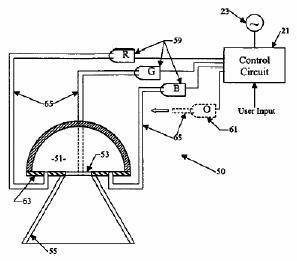
As disclosed herein, an apparatus for emitting radiant energy includes an integrating cavity, having a diffusely reflective interior surface and an aperture for allowing emission of integrated radiant energy. Sources supply radiant energy into the interior of the integrating cavity. At least two of the sources emit radiant energy of different wavelengths. The cavity effectively combines the energy of different wavelengths, so that the radiant energy emitted through the aperture includes the radiant energy of the various wavelengths. The apparatus also includes a control circuit coupled to the sources for establishing output intensity of radiant energy of each of the sources. Control of the intensity of emission of the sources sets a spectral characteristic of the combined radiant energy emitted through the aperture.
In the examples, the points of entry of the energy from the sources into the cavity are located so that the emission points are not directly visible through the aperture. Each source typically comprises one or more light emitting diodes (LEDs). It is possible to install any desirable number of LEDs. Hence, In several examples, the sources may comprise one or more LEDs for emitting light of a first color, and one or more LEDs for emitting light of a second color, wherein the second color is different from the first color. In a similar fashion, the apparatus may include additional LED sources of a third color, a fourth color, etc. To achieve the highest color-rendering index (CRI), the LED array may include LEDs of colors that effectively cover the entire visible spectrum.
These sources can include any color or wavelength, but typically include red, green, and blue. The integrating or mixing capability of the chamber serves to project light of any color, including white light, by adjusting the intensity of the various sources coupled to the cavity. Hence, it is possible to control color rendering index, as well as color temperature. The system works with the totality of light output from a family of LEDs. However, to provide color adjustment or variability, it is not necessary to control the output of individual LEDs, except as the intensity of each contributes to the totality. For example, it is not necessary to modulate the LED outputs. Also, the distribution pattern of the LEDs is not significant. The LEDs can be arranged in any manner to supply radiant energy within the chamber, although typically direct view from outside the fixture is avoided.
The LED sources may be coupled to openings at the points on the interior of the cavity, to emit radiant energy directly into the interior of the integrating cavity. It is also envisioned that the sources may be somewhat separated from the cavity, in which case, the device might include optical fibers coupled between the sources and the integrating cavity, to supply radiant energy from the sources to the emission points into the interior of the cavity.
In the disclosed examples, the apparatus further comprises a conical deflector. A small opening at a proximal end of the deflector is coupled to the aperture of the integrating cavity. The deflector has a larger opening at a distal end thereof. The deflector comprises a reflective interior surface between the distal end and the proximal end. In the examples, at least a substantial portion of the reflective interior surface of the conical deflector exhibits specular reflectivity with respect to the combined radiant energy. The conical deflector defines an angular field of radiant energy emission from the apparatus.
An exemplary system includes a number of "sleeper" LEDs that would be activated only when needed, for example, to maintain the light output, color, color temperature or thermal temperature. Hence, examples are also disclosed in which the first color LEDs comprise one or more initially active LEDs for emitting light of the first color and one or more initially inactive LEDs for emitting light of the first color on an as needed basis. Similarly, the second color LEDs include one or more initially active LEDs for emitting light of the second color and one or more initially inactive LEDs for emitting light of the second color on an as needed basis. In a similar fashion, the apparatus may include additional active and inactive LED sources of a third color, fourth color, etc.
As noted in the background, as LEDs age or experience increases in thermal temperature, they continue to operate, but at a reduced output level. The use of the sleeper LEDs greatly extends the lifecycle of the fixtures. Activating a sleeper (previously inactive) LED, for example, provides compensation for the decrease in output of the originally active LED. There is also more flexibility in the range of intensities that the fixtures may provide.
A number of different examples of control circuits are discussed below. In one example, the control circuitry comprises a color sensor coupled to detect color distribution in the combined radiant energy. Associated logic circuitry, responsive to the detected color distribution, controls the output intensity of the various LEDs, so as to provide a desired color distribution in the integrated radiant energy. In an example using sleeper LEDs, the logic circuitry is responsive to the detected color distribution to selectively activate the inactive light emitting diodes as needed, to maintain the desired color distribution in the combined radiant energy.
A number of other control circuit features also are disclosed. For example, the control circuitry may also include a temperature sensor. In such an example, the logic circuitry is also responsive to the sensed temperature, e.g. to reduce intensity of the source outputs to compensate for temperature increases.
The control circuitry may include an appropriate device for manually setting the desired spectral characteristic, for example, one or more variable resistors or one or more dip switches, to allow a user to define or select the desired color distribution.
Automatic controls also are envisioned. For example, the control circuitry may include a data interface coupled to the logic circuitry, for receiving data defining the desired color distribution. Such an interface would allow input of control data from a separate or even remote device, such as a personal computer, personal digital assistant or the like. A number of the devices, with such data interfaces, may be controlled from a common central location or device.
The control may be somewhat static, e.g. set the desired color reference index or desired color temperature and the overall intensity and leave the device set-up in that manner for an indefinite period. The apparatus also may be controlled dynamically, for example, to vary the color of the combined light output and thereby provide special effects lighting. Where a number of the devices are arranged in a large two-dimensional array, dynamic control of color and intensity of each unit could even provide a video display capability, for example, for use as a "Jumbo-Tron" view screen in a stadium or the like.
The disclosed apparatus may use a variety of different structures or arrangements for the integrating cavity. It is desirable that the interior cavity surface have a highly efficient diffusely reflective characteristic, e.g. a reflectivity of over 90%, with respect to the relevant wavelengths, in order to maximize optical efficiency. In several examples, the cavity is formed of a diffusely reflective plastic material, such as a polypropylene having a 98% reflectivity and a diffuse reflective characteristic. Another example of a material with a suitable reflectivity is SPECTRALON. Alternatively, the integrating cavity may comprise a rigid substrate having an interior surface, and a diffusely reflective coating layer formed on the interior surface of the substrate so as to provide the diffusely reflective interior surface of the integrating cavity.
A variety of different shapes may be used for the interior reflective surface of the cavity. Although it may be rectangular, triangular or in the shape of a pyramid, in the examples, the diffusely reflective interior surface of the integrating cavity has a shape corresponding to a substantial portion of a sphere (e.g. hemispherical) or a substantial portion of a cylinder (e.g. approximating a half-cylinder).
To provide a uniform output distribution from the apparatus, it is also possible to construct the cavity so as to provide constructive occlusion. Constructive Occlusion type transducer systems utilize an electrical/optical transducer optically coupled to an active area of the system, typically the aperture of a cavity or an effective aperture formed by a reflection of the cavity. The systems utilize diffusely reflective surfaces, such that the active area exhibits a substantially Lambertian characteristic. A mask occludes a portion of the active area of the system, in the examples, the aperture of the cavity or the effective aperture formed by the cavity reflection, in such a manner as to achieve a desired response or output characteristic for the system. In examples of the present apparatus using constructive occlusion, the integrating cavity would include a base, a mask and a cavity formed in the base or the mask. The mask would have a diffusely reflective surface. The mask is sized and positioned relative to the active area of the system so as to constructively occlude the active area.
In one example of the present apparatus using constructive occlusive, the device would further include a mask outside the integrating cavity formed in the base. The mask would have a diffusely reflective surface facing toward the aperture of the cavity. The mask is sized and positioned relative to the aperture so as to constructively occlude the aperture. In another constructive occlusion example, the aperture that serves as the active area is actually a reflection of the interior surface of a dome that forms the curved interior of the cavity. The reflection is formed on a base surface opposite the cavity of the dome. The interior of the cavity is diffusely reflective. In this later arrangement, the dome also serves as the constructive occlusion mask.
The inventive devices have numerous applications, and the output intensity and spectral characteristic may be tailored and/or adjusted to suit the particular application. For example, the intensity of the integrated radiant energy emitted through the aperture may be at a level for use in a rumination application or at a level sufficient for a task lighting application.
Additional objects, advantages and novel features of the examples will be set forth in part in the description which follows, and in part will become apparent to those skilled in the art upon examination of the following and the accompanying drawings or may be learned by production or operation of the examples. The objects and advantages of the present subject matter may be realized and attained by means of the methodologies, instrumentalities and combinations particularly pointed out in the appended claims.
Claims
1. An apparatus for emitting visible light of multiple wavelengths comprising: a light fixture having a cavity; first, second and third light emitting diodes (LEDs) for emitting visible light of different first, second and third wavelengths, respectively, for combination within the cavity of the light fixture in such a manner that the cavity emits combined light; a color sensor coupled to the cavity for detecting color distribution in the combined light within the cavity; and control circuitry responsive to the color distribution detected by the color sensor, for controlling output of visible light of each of the LEDs to set a spectral characteristic of the combined light.
2. The apparatus of claim 1, further comprising means for diffusing visible light of the first, second and third wavelengths to form the combined light within the cavity of the light fixture.
3. The apparatus of claim 2, wherein: the means for diffusing comprises a diffusely reflective surface of the cavity; and the diffusely reflective cavity surface forms an optical integrating chamber having an aperture for emission of the combined light from the light fixture.
4. An apparatus for emitting visible light of multiple wavelengths, comprising: a light fixture having a cavity; first, second and third light emitting diodes (LEDs) for emitting visible light of different first, second and third wavelengths, respectively, through the cavity of the light fixture; a color sensor for detecting color distribution in combined light from the LEDs within the cavity; control circuitry responsive to the color distribution detected by the color sensor, for controlling output of visible light of each of the LEDs to set a spectral characteristic of combined light emitted from the light fixture; and an initially inactive LED, wherein the controller is configured to activate the initially inactive LED responsive to the color distribution detected by the color sensor, as needed, to maintain the spectral characteristic of combined light emitted from the light fixture.
5. An apparatus for emitting visible light of multiple wavelengths, comprising: a light fixture having a cavity; first, second and third light emitting diodes (LEDs) for emitting visible light of different first, second and third wavelengths, respectively, through the cavity of the light fixture; a color sensor for detecting color distribution in combined light from the LEDs within the cavity; control circuitry responsive to the color distribution detected by the color sensor, for controlling output of visible light of each of the LEDs to set a spectral characteristic of combined light emitted from the light fixture; and first, second and third initially inactive LEDs for emitting visible light of the different first, second and third wavelengths, respectively, through the cavity of the light fixture, wherein the controller is configured to activate the initially inactive LEDs responsive to the color distribution detected by the color sensor, as needed, to maintain the spectral characteristic of combined light emitted from the light fixture.
6. An apparatus for emitting light, comprising: a first of source of humanly visible light of a first wavelength; a second source of humanly visible light of a second wavelength, the second wavelength being different from the first wavelength; a chamber having a reflective interior surface for receiving and combining light of the first and second wavelengths from the sources within the chamber so as to form combined light containing both light of the first wavelength and light of the second wavelength, the chamber having a light path allowing emission of at least some of the combined light; a color sensor coupled to the chamber for detecting color in the combined light within the chamber; and control circuitry for controlling output of at least one of the sources responsive to the color detected by the color sensor.
7. The apparatus of claim 6, wherein: the chamber comprises a cavity, the reflective interior surface comprises a diffusely reflective surface of the cavity, and diffuse reflection within the cavity optically integrates light of the first and second wavelengths within the chamber before emission as combined light via the light path.
8. The apparatus of claim 7, wherein the light path comprises an opening of the cavity.
9. An apparatus for emitting light, comprising: a first of source of humanly visible light of a first wavelength; a second source of humanly visible light of a second wavelength, the second wavelength being different from the first wavelength; a chamber having a reflective interior surface for receiving and combining light of the first and second wavelengths from the sources, and having a light path allowing emission of combined light containing both light of the first wavelength and light of the second wavelength; a color sensor for detecting color in the combined light; control circuitry for controlling output at least one of the sources responsive to the color detected by the color sensor; a first initially inactive source of visible light of the first wavelength; and a second initially inactive source of visible light of the second wavelength, wherein the controller is configured to selectively activate the first and second initially inactive, sources responsive to the color detected by the color sensor, as needed to maintain a spectral characteristic of the combined light.
10. A lighting apparatus comprising: a first light emitting diode (LED); a second LED for emitting light of a characteristic substantially similar to a characteristic of the light emitted by the first LED; a controller coupled to control operation of the first and second LEDs, such that the first LED is initially active and the second LED is initially inactive; and a sensor arranged to sense at least one condition relating to operation of the apparatus, wherein the controller is configured to selectively activate the second LED in response to the condition sensed by the sensor, so as to compensate for a decrease in performance of the first LED.
11. The apparatus of claim 10, further comprising an optical integrating chamber for combining light from the first and second LEDs and providing a combined light output.
12. The apparatus of claim 10, further comprising: a third LED for emitting light of a characteristic substantially different from the characteristic of the light emitted by the first LED; and a fourth LED for emitting light of a characteristic substantially similar to the characteristic of the light emitted by the third LED; wherein: the controller is coupled to control operation of the third and fourth LEDs, such that the third LED is initially active and the fourth LED is initially inactive, and the controller is configured to selectively activate the third LED in response to the condition sensed by the sensor, so as to compensate for a decrease in performance of the third LED.
13. The apparatus of claim 12, wherein: the first and second LEDs are for emission of light of a first color; and the second and third LEDs are for emission of light of a second color different from the first color.
14. The apparatus of claim 13, further comprising an optical integrating chamber for combining light from the first, second third and fourth LEDs and providing a combined light output containing light of the first and second colors.
15. The apparatus of claim 13, wherein the sensor comprises a color sensor for detecting color distribution in light produced by the LEDs.
16. A method of providing illumination with light of a desired color characteristic, comprising: generating an amount of light of a first wavelength; generating an amount of light of a second wavelength, wherein the second wavelength is different from the first wavelength; reflecting at least some of the generated light of the first and second wavelengths within a reflective chamber, to produce combined light containing light of the first and second wavelengths; sensing a color characteristic of the combined light within the reflective chamber; controlling the generated amount of light of at least one of the first and second wavelengths in response to the sensed characteristic of the combined light within the reflective chamber, in such a manner that the combined light exhibits the desired color characteristic; and emitting at least a portion of the combined light from the reflective chamber to provide illumination.
17. The method of claim 16, wherein: the reflective chamber comprises an optical integrating cavity; the reflecting comprises diffusely reflecting at least some of the generated light of the first and second wavelengths within the optical integrating cavity; and the emitting comprises emitting at least a portion of the combined light via an aperture of the cavity.
18. A method of providing illumination with light of a desired color characteristic, comprising: generating an amount of light of a first wavelength; generating an amount of light of a second wavelength, wherein the second wavelength is different from the first wavelength; reflecting at least some of the generated light of the first and second wavelengths, to produce combined light containing light of the first and second wavelengths; sensing a characteristic of the combined light; controlling the generated amount of light of at least one of the first and second wavelengths in response to the sensed characteristic of the combined light, in such a manner that the combined light exhibits the desired color characteristic; emitting at least a portion of the combined light to provide illumination; detecting a decrease in performance of an active first source used in the generating of the light of the first wavelength; and activating a previously inactive second source of light of the first wavelength, to compensate for the decrease in performance of the first source.
19. A method of providing illumination from a lighting system, comprising: operating a first light emitting diode (LED) of the lighting system to provide illumination, wherein a second LED of the lighting system is initially not operating; detecting an operational condition of the lighting system indicative of performance of at least the first LED; and initiating operation of the second LED in response to the detected condition indicating a decrease in performance of the first LED.
20. The method of claim 19, further comprising optically combining at least portions of light outputs from the first and second LEDs.
21. The method of claim 20, wherein the optically combining comprises: diffusely reflecting at least portions of the light outputs from the first and second LEDs within a reflective cavity; and emitting combined light from the cavity.
22. The method of claim 19, wherein the first and second LEDs emit light of a first color and the method further comprises: operating a third LED of the lighting system to provide light of a second color different from the first color, wherein a fourth LED of the lighting system for providing light of the second color is initially not operating; and initiating operation of the fourth LED in response to the detected condition indicating a decrease in performance of the third LED.
23. The method of claim 22, further comprising optically combining at least portions of light outputs of the first and second colors from the operating LEDs.
24. The method of claim 23, wherein the optically combining comprises: diffusely reflecting at least portions of the light outputs from the operating LEDs within a reflective cavity; and emitting combined light from the cavity.
See full document in pdf.
