Off-Line LED Control Circuit
Resonant mode topologies offer many benefits over traditional buck, boost and flyback solutions. These include soft-switching, higher operating frequencies, higher power density and higher efficiency. Electronic ballast designs for fluorescent lighting applications have already been taking advantage of these benefits for many decades. Much can be learned from electronic ballast circuits and applied to LED driver circuits. This article compares the load requirements for fluorescent lamps and LEDs, explains the functionality of a new dimming electronic ballast control IC, and describes a new resonant mode control circuit for LEDs that uses the new IC. Experimental results of the new circuit are also presented and summarized to show final performance.


Fluorescent vs. LEDs
Fluorescence is the conversion of UV light to visible light. Electrons flow through the fluorescent lamp and collide with mercury atoms causing photons of UV light to be released. The UV light is then converted into visible light as it passes through the phosphor coating on the inside of the glass tube wall. This two-stage conversion process results in about 25% of the total energy consumed by the lamp being used to generate light. A typical fluorescent lamp also has a low lamp running temperature (40degC) and a lifetime of about 10,000 hours. To control a fluorescent lamp, the lamp requires a voltage or current to preheat the filaments, a high-voltage for ignition, and a high-frequency AC current during running.
LEDs work on a completely different principle than fluorescent lamps. Individual electrons jump across a p-n junction (from the n-type region to the p-type) of a semiconductor material. The ‘band-gap’ in certain semiconductors such as gallium is very wide and requires appreciable energy to make electrons jump across the junction. When each electron recombines with an atom, it emits a particle of light known as a photon. Because all of the light is being produced in a very small space down at the junction, the resulting light source is a point source and requires many LEDs to light a large area. Also, the heat inside an LED cannot be thermally dissipated by the LED itself resulting in high LED working temperatures and therefore requires heatsinking.
LEDs are much simpler to control but still have their own set of requirements and challenges. They do not need to be ignited or preheated but the current should be constant and matched in each LED. Also, depending on the application, the electrical connection to the LEDs may or may not need to be galvanically isolated. The circuit requirements for fluorescent and LED have been summarized for comparison (Table 1).
IRS2530D “DIM8 TM” Control IC
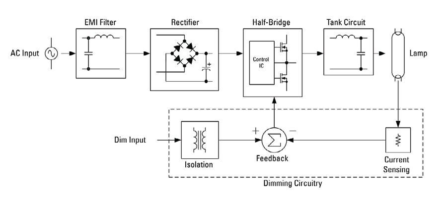
Existing ballast non-dimming circuits include (Figure 1) an input filter for blocking ballast generated noise, a rectifier and smoothing capacitor for converting the AC line input into a DC bus voltage, a control IC and half-bridge for producing a high-frequency square-wave voltage, and a resonant output stage for preheating, igniting and running the fluorescent lamp. The additional circuitry needed for dimming includes (Figure 1) an isolated 0-to-10VDC dimming interface, a current-sensing circuit to measure the lamp current, and a closed-loop feedback circuit to keep the lamp current regulated to the user setting by continuously adjusting the output frequency. A closed-loop system is needed to regulate the lamp current due to the non-linear electrical characteristics of the fluorescent lamp.
The IRS2530D (Figure 2) is a 600V, 8-pin fluorescent dimming control IC that provides the high- and low-side gate drive for the half-bridge, includes all of the dimming ballast functions, and protects the circuit against line and load fault conditions. The IC already uses 6 pins for very basic but necessary functions: IC supply and ground (VCC, COM), and, half-bridge high- and low-side gate drive (VB, HO, VS, LO). The challenge is then to realize the other functions -- preheat, ignition and dimming - with only two remaining pins (VCO, DIM).
When a voltage is first applied to VCC (14V, typical) the IC exits UVLO mode and enters Preheat/Ignition mode. The half-bridge begins oscillating at the maximum frequency and the internal current source at the VCO pin begins charging up an external capacitor (CVCO) linearly from COM (Figure 3). The output frequency decreases as the VCO voltage increases and the lamp filaments are preheated by secondary windings from the resonant tank inductor. As the VCO voltage charges up, the frequency decreases towards the resonance frequency of the resonant tank circuit and the output voltage across the lamp increases. The lamp ignites when the output voltage exceeds the lamp ignition threshold voltage, lamp current begins to flow, and the IC enters Dim mode.
During Dim mode, a current sense resistor (RCS) is used to measure the AC lamp current. This AC measurement is then coupled to the DC reference at the DIM pin through a feedback capacitor (C2). The AC + DC signal at the DIM pin is then compared to COM internally to the IC and the frequency is controlled such that the valleys of the AC component are held at COM continuously (Figure 4). As the DC reference is increased or decreased while the AC valleys are held at COM, the AC lamp current amplitude will then increase or decrease as well. By combining the DC reference with the AC lamp current, a single pin can then be used for both reference and feedback functions to achieve closed-loop dimming control.
See Figure 4 (see LpR magazine)
New LED Control Circuit
Typical LED control circuits are designed around a buck, boost or flyback topology, and they are used to generate a constant DC current through a string of a given number of LEDs. Each of these topologies has advantages and disadvantages depending on the input voltage range, the number of LEDs being driven in series, the number of parallel LED strings, the LED output current, if isolation is required, if dimming is required, efficiency, size and cost. For this reason, many circuit variations exist to satisfy the many different LED applications. The new circuit is a resonant mode circuit that has been slightly modified from dimming fluorescent applications. It is for non-isolated, off-line applications, and can drive one or many LEDs in series, can be easily scaled for different LED current levels, and utilizes soft-switching for good efficiency. The new circuit (Figure 5) is designed around the existing IRS2530D Dimming Control IC, and the output stage has been modified to drive LEDs instead of a fluorescent lamp. It is no longer necessary to preheat and ignite the load so the resonant tank has been changed to a series L-C-LED type (instead of a series L, parallel R-C for fluorescent). Since the output current is AC, a full-wave bridge rectifier has been added to the output so that current is always flowing through the LEDs during each highfrequency switching cycle.
The AC current sensing is still performed using a resistor (RCS) that is placed in between the bottom of the rectifier and COM, and gives a direct AC measurement of the full-wave rectified LED current amplitude. This AC measurement is then coupled onto the DIM pin through resistor RFB and capacitor CFB. The dimming control loop of the IRS2530D then keeps the amplitude of the LED current regulated by continuously adjusting the frequency of the half-bridge switching circuit such that the nominal r.m.s. LED current is maintained within the manufacturer’s specifications. If the LED current decreases, then the loop decreases the frequency. This will increase the gain of the resonant tank circuit and increase the LED current. If the LED current increases, then the loop increases the frequency. This will decrease the gain of the resonant tank circuit and decrease the LED current. The dimming control loop keeps the LED current constant over line, load and temperature variations, and will work for a single LED or many LEDs in series.
See Figure 5 (see LpR magazine)
Experimental Results
The experimental results show the waveforms during normal start-up and running conditions (Figures 6 and 7). When the AC line voltage is first applied, VCC charges up and the IC turns on. The output frequency starts at the maximum frequency of the IC and sweeps down towards the resonant frequency of the series L-C-LED resonant circuit. The frequency sweep is performed by the capacitor CVCO at the VCO pin. The LED current (sensed through resistor RCS) increases as the frequency decreases. This causes the amplitude of the AC signal at the DIM pin to also increase until the valley of the AC signal reaches COM (Figure 6). The IC then enters Dim mode and enables the dimming loop. The dimming loop continuously adjusts the output frequency to keep valley of the AC signal at the DIM pin maintained at COM and therefore maintains a constant LED current amplitude. The LED current (Figure 7) is full-wave rectified and operates at twice the frequency of the halfbridge switching node (VS pin). The shape of the LED current waveform is sinusoidal due to the resonant behavior of the circuit. This helps keep the current crest factor low so that the nominal LED r.m.s. current is achieved without excessive peak currents.
The IRS2530D also includes additional circuitry for protection against all line and load fault conditions. These include AC mains brown-out, open circuit (no load or LED failure) and short circuit fault conditions.
See Figure 6 (see LpR magazine)
See Figure 7 (see LpR magazine)
Conclusion
The new off-line LED control circuit is simple and provides good constant current regulation for the LEDs. It is easily scalable for different input voltage ranges and LED current levels, and is flexible to the number of LEDs connected at the output. The IRS2530D successfully drives circuit for both fluorescent and LED applications. The IC integrates the complete control in a low-cost, 8-pin solution, and the control loop delivers good constant current performance over all line and load conditions, and the IC detects all fault conditions and deactivates the circuit safely. Additional circuit improvements to be considered include PWM on/off dimming of the LEDs.
