Dimming Control Circuit for Light-Emitting Diodes
A dimming control circuit generates a dimming control signal for determining brightness of at least one light-emitting diode. The dimming control signal has a plurality of bright-dark cycles, each of which consists of a bright phase and a dark phase. The bright phase starts with an adaptive rising portion. The adaptive rising portion restricts the brightness of the at least one light-emitting diode to increase gradually from zero.

Background of the invention
1. Field of the Invention
The present invention relates to a dimming control circuit and, more particularly, to a dimming control circuit applied to a drive circuit for driving light-emitting diodes.
2. Description of the Prior Art
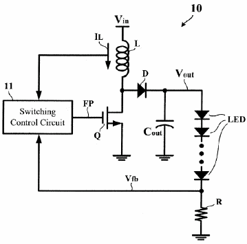
FIG. 1 is a circuit diagram showing a conventional light-emitting diode drive circuit 10. In the example of FIG. 1, the light-emitting diode drive circuit 10 is implemented by a boost-type switching voltage regulator for converting an input voltage V.sub.in into an output voltage V.sub.out desired for driving one or more series-connected light-emitting diodes LED. In accordance with a current I.sub.L flowing through an inductor L and a feedback voltage V.sub.fb from a resistor R, a switching control circuit 11 generates a fixed-duty pulse drive signal FS for turning on/off a switching transistor Q. The duty ratio of the switching transistor Q determines the proportional relationship between the output voltage V.sub.out and the input voltage V.sub.in. The brightness of the light-emitting diodes LED varies depending on the diode current I.sub.LED flowing through themselves. From FIG. 1 is derived an equation regarding to the diode current I.sub.LED: I.sub.LED=V.sub.fb/R=(V.sub.out-N*V.sub.d)/R, where N is the number of the light-emitting diodes and V.sub.d is a voltage drop of one single conductive light-emitting diode. Since the voltage drop V.sub.d may be considered approximately constant, the diode current I.sub.LED as well as the brightness of the light-emitting diodes LED is easily controlled by the adjustment to the output voltage V.sub.out.
Another method of controlling the brightness of the light-emitting diodes LED appeals to the nature of human-eye perceptions. For bright-dark cycles alternating over about 60 Hz, the human eyes perceive an average brightness instead of flickering. In the bright phase the switching transistor Q is, as conventional, turned on/off by the fixed-duty pulse drive signal FS from the switching control circuit 11, but in the dark phase the fixed-duty pulse drive signal FS is blocked in order to keep the switching transistor Q nonconductive. In other words, through controlling the ratio of the bright phase to the dark phase, the desired average brightness is achieved. However, such a dimming method by using bright-dark cycles causes a huge current noise peak at the beginning of each bright phase. Because the frequency of the bright-dark cycles may be set within the audio-frequency range, the serially-occurred current noise peaks actually produce noisy sounds to human ears.
Brief summary of the invention
In view of the above-mentioned problems, an object of the present invention is to provide a dimming control circuit for light-emitting diodes, capable of reducing current noise peaks at the beginning of each bright cycle.
According to a first aspect of the present invention, a dimming control circuit generates a dimming control signal to determine a brightness of at least one light-emitting diode. The dimming control signal has a plurality of bright-dark cycles, each of which consists of a bright phase and a dark phase. The bright phase starts with an adaptive rising portion for restricting the brightness of the at least one light-emitting diode to increase gradually.
According to a second aspect of the present invention, a light-emitting diode drive circuit includes a switching control circuit, a switching voltage regulator, and a dimming control circuit. The switching control circuit generates a pulse drive signal. The switching voltage regulator is controlled by the pulse drive signal for driving at least one light-emitting diode. The dimming control circuit generates a dimming control signal to restrict a switching duty ratio of the pulse drive signal through the switching control circuit. The dimming control signal has a plurality of bright-dark cycles, each of which consists of a bright phase and a dark phase. The bright phase starts with an adaptive rising portion for restricting the switching duty ratio of the pulse drive signal to increase gradually.
According to a third aspect of the present invention, a light-emitting diode drive chip includes a pin, a control circuit, and an enabling circuit. The pin receives a brightness/shutdown signal. The control circuit generates a dimming signal in response to the brightness/shutdown signal so as to control a brightness of at least one light-emitting diode. The dimming signal has a plurality of bright-dark cycles, each of which consists of a bright phase and a dark phase. The bright phase starts with an adaptive rising portion for restricting the brightness of the at least one light-emitting diode to increase gradually. The enabling circuit generates an enable signal in response to the brightness/shutdown signal such that the enable signal activates the control circuit in the bright phase and terminates the control circuit when the dark phase exceeds a predetermined threshold time.
These and other objectives of the present invention will no doubt become obvious to those of ordinary skill in the art after reading the following detailed description of the preferred embodiment that is illustrated in the various figures and drawings.
Claims
1. A light-emitting diode drive circuit comprising: a switching control circuit for generating a pulse drive signal; a switching voltage regulator controlled by the pulse drive signal for driving at least one light-emitting diode; and a dimming control circuit for generating a dimming control signal to restrict a switching duty ratio of the pulse drive signal through the switching control circuit, wherein: the dimming control signal has a plurality of bright-dark cycles, each of which consists of a bright phase and a dark phase, the bright phase starting with an adaptive rising portion for restricting the switching duty ratio of the pulse drive signal to increase gradually.
2. The circuit according to claim 1, wherein: the adaptive rising portion is determined in accordance with a dark phase of a previous bright-dark cycle.
3. The circuit according to claim 2, wherein: the adaptive rising portion is longer when the dark phase of the previous bright-dark cycle is longer.
4. The circuit according to claim 1, further comprising: a logic unit for preventing the pulse drive signal from being applied to the switching voltage regulator in the dark phase, and for allowing the pulse drive signal to be applied to the switching voltage regulator in the bright phase.
5. The circuit according to claim 1, further comprising: an enabling circuit for activating the switching control circuit and the dimming control circuit in the bright phase, and for terminating the switching control circuit and the dimming control circuit when the dark phase exceeds a predetermined threshold time.
6. A light-emitting diode drive chip, comprising: a pin for receiving a brightness/shutdown signal; a control circuit for generating a dimming signal in response to the brightness/shutdown signal so as to control a brightness of at least one light-emitting diode, the dimming signal having a plurality of bright-dark cycles, each of which consists of a bright phase and a dark phase, the bright phase starting with an adaptive rising portion for restricting the brightness of the at least one light-emitting diode to increase gradually; and an enabling circuit for generating an enable signal in response to the brightness/shutdown signal such that the enable signal activates the control circuit in the bright phase and terminates the control circuit when the dark phase exceeds a predetermined threshold time.
7. The chip according to claim 6, wherein: the adaptive rising portion is determined in accordance with a dark phase of a previous bright-dark cycle.
8. A dimming control circuit generating a dimming control signal to determine a brightness of at least one light-emitting diode, the dimming control signal having a plurality of bright-dark cycles, each of which consists of a bright phase and a dark phase, the bright phase starting with an adaptive rising portion for restricting the brightness of the at least one light-emitting diode to increase gradually.
9. The circuit according to claim 8, wherein: the adaptive rising portion is determined in accordance with a dark phase of a previous bright-dark cycle.
10. The circuit according to claim 9, wherein: the adaptive rising portion is longer when the dark phase of the previous bright-dark cycle is longer.
See full document in pdf.
