Diode Lighting System
A lighting system for stage, theatrical and architectural lighting, comprising a frame for supporting a plurality of light emitting diodes. The diodes are mounted to the frame so that each diode is both secured to the frame and also simultaneously positioned wherein each discrete diode light beam is directed to a prescribed remote focal point (target zone) and thereupon directed to a predetermined illumination area. Electrical power for transmitting and controlling electrical voltage to light emitting diodes by electrical circuitry integral with the frame. The frame can be configured as any hollow volume such a cone, a semi-ellipse, and a semi-sphere or can be configured as planar. Flexible blanks having apertures and pads for electrical connections can be used to construct rigid frames. An imaging gate a collimating lens and a focusing lens can be interposed between the frame and the illumination area. The frame can also be a sandwich frame having positive and negative electrically conductive layers interposed between layers of biasable insulating foam.

Background of the invention
Incandescent and halogen type lamps have been widely used in various conventional lighting devices for the projection of light onto a surface for illumination and for general illumination purposes. Such lamps depend on the heating of a tungsten wire filament to a high temperature and therefore emit light. These lamps are not energy efficient and they generate excessive heat.
Illuminating light sources such as metal halide arc lamps, gas discharge lamps, fluorescent lamps and halogen light bulbs, as examples, have been widely used in various conventional lighting devices for the projection of light onto a surface for illumination. Such light sources are used in architectural, theatrical and stage lighting systems as well as in industrial applications for lighting surfaces, scenery, an object, or a person. These light sources are also used to project a sharp image of a gobo, shutter cut, or pattern onto a surface when such items are placed at the gate aperture of lighting devices somewhere between the light source and a lens lighting system.
These image projection and lighting systems are typically called ellipsoidals. Conventional lighting systems comprise an ellipsoidal reflector used with a single high-intensity lamp, an imaging gate, and light collection lenses, including focusing lenses and collimating lenses. A single ellipsoidal reflector is used because it enhances light collection in the most efficient configuration known in the art of light projection. By definition, an ellipse has two focal points. The curve of an ellipsoidal reflector is matched with the light source to produce an exact focused secondary image of the light source at the same distance at which it is located from the reflector at the opposite end. When a light source is placed at the primary focal point of the reflector, the ellipsoidal reflector reflects or redirects, the light to the secondary focal point in front of the reflector. Multi-facets on the inside surface of the ellipsoidal reflector project the light beams to the secondary focal point.
Conventional light sources have shortcomings. They generate a large amount of heat and so consume a large amount of energy, with the result that lamp life is short. In addition, lighting systems that use the conventional light sources suffer from the excess amount of heat that is transferred to the exterior of the fixture housing. Likewise, the use of the incandescent filament lamps and arc lamps in conventional ellipsoidal projection lighting systems transfer a high degree of heat to the fixtures. The primary reason for this heat loss is that a major part of the light energy is in fact wasted as infrared heat energy. The use of cold mirror coated reflectors has helped somewhat, but these fixtures continue to have low energy efficiency. An additional problem with conventional light sources is that they have low resistance to vibration.
An alternate light source is the light emitting diode (LED). Advancements have been made in LED technology and in the overall use of LEDs. LEDs have several different characteristics that set them apart from conventional light emitting technology. As one example, an LED used in place of a conventional light source will produce a cooler, longer running, and more energy efficient lighting fixture. A disadvantage of LEDs when compared to incandescent and halogen lamps is their relatively low illumination intensity. A basic characteristic of LEDs that sets them apart from conventional light emitting technology is that while conventional lamps radiate light into the surrounding hemisphere with relatively equal intensity in all directions, light emitting diode lamps with their substantially planar luminescent elements radiate high intensity light primarily in the forward direction resulting in only minimal quantities of light energy radiated to the sides. It is to be noted, however, that LEDs are presently manufactured with integral lenses molded into the diode housings just in front of the diode chip. Even with the lenses, however, LEDs are available only with some degree of beam spread, or angle. Beam spreads of a LED, shown in FIG. 1 herein for purposes of exposition only, vary according to the manufacturer generally between approximately 5 and 70 degrees. Despite there being some degree of beam spread, LEDs are much more centered than conventional lamp technology. For purposes of clarity, FIG. 2 shows a straight line representing the virtual center of a typical LED beam.
The solid state design of LEDs allows them to be more durable and robust, and lets them withstand shock, vibration, frequent power cycling, and extreme temperatures. LEDs have an average usable life of typically 100,000 hours or more when they are operated within their electrical specifications. In comparison, incandescent filament lamps generate high-intensity light for only a short time, typically a few hundred hours, and are very susceptible to damage from both shock and vibration.
Red, green, and blue (RGB) LEDs are known in the art. It is noted that color gel filters used with conventional light source technology are not necessary in diode technology because RGB LEDs are capable of serving as a full color spectrum generating light source. The primary colors red, green, and blue of RGB LEDs can be mixed to produce the secondary colors cyan, yellow, magenta (CYM), and also white light. Mixing green and blue gives cyan, as is known in the art of colors. Likewise as is known in the art, mixing green and red gives yellow. Mixing red and blue gives magenta. Mixing red, green, and blue together results in white. Advances in light-emitting diode technology include the development of multi-chip and multi-LED arrays, which have led to brighter LEDs available in different colors. LEDs are available in both visible colors and infrared. In addition to red, yellow, and amber/orange, which were the first available colors, LEDs are also available in green, blue, and even white light. Clearly, for many applications, light-emitting diodes can compete directly with incandescent filament light sources.
While incandescent filament lamps give off the full spectrum of light, LEDs can emit focused discrete beams of color at a variety of different angles. Color efficiency in LEDs is much better than it is for incandescent filament lamps. In order to get color from an incandescent filament lamp, a specific color gel or filter in that particular color spectrum has to be used. This can waste 90 percent and more of the incandescent filament lamp's light energy. In comparison, LEDs deliver 100% of their energy as light and give a more intense colored light. This efficiency also gives LEDs the advantage of white light as well.
LED lamps have been considered for many lighting devices because of their long life, high luminous efficiency, and intrinsic colors. However, their use has been limited to low intensity devices because individually, they emit only small quantities of light energy. It has not been possible to efficiently combine a plurality of LED lamps into a single lighting device comprising a number of LEDs of limited size together capable of emitting a concentrated light beam meeting specific intensity, beam spread, power consumption, and size requirements that is related to large scale lighting arts such as architectural displays, and theatrical and stage productions.
Summary of the invention
Accordingly, the object of the present invention is to provide an illuminating device that uses substantially the maximum number of LEDs possible that are compactly arranged in close mutual proximity onto a curved surface.
The above object is accomplished by a unique structure for a LED illuminating device of the present invention which includes a larger array of LEDs that are compactly arranged in close proximity along the inside surface of a substantially ellipsoidal-type housing or a housing having a configuration that is related to an ellipsoidal-type housing with the light rays from the LEDs being directed to a single focal region.
It is another object of the invention to devise an arrangement for focusing a plurality of LEDs mounted on any type of surface into a single focal region with all the LEDs being directed to a single focal region.
It is a further object of this invention to maximize the number of LEDs within any suitably confined volume by arranging the LEDs in an array on the inner surface of the volume so as to obtain the most efficient and brightest possible light output.
It is yet another object of this invention to use an LED light source in combination with an imaging gate and lenses to create an energy efficient and longer-lasting lighting system.
It is yet another object of this invention to use individual LED light sources mounted in a hollow volume configured in any of several known geometric configurations that efficiently direct the light beams emitted by each of the LEDs to a common focal point, or target zone, for the purpose of organizing the individual LED light sources into a single total LED generated light beam.
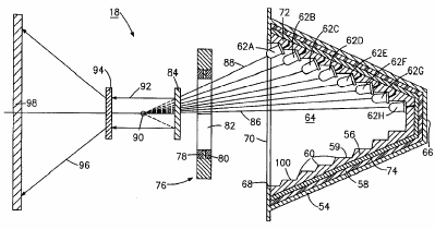
In accordance with these and other objects that will be made evident in the course of this disclosure, there is provided a lighting system for architectural, theatrical and stage lighting including a frame for supporting a plurality of light emitting diodes (LEDs) for generating a plurality of substantially forward-directed light beams to a prescribed focal point, or target zone so that an organized diode-generated light beam is directed from the target zone to an illumination area. The diode frame can be configured as a hollow volume of various geometrical configurations such as semi-ellipsoidal shaped, cone-shaped, and semi-spherical shaped. The diode frame can also be planar. An imaging gate aperture, a collimating lens and a focusing lens can be included in the illumination lighting system. A flexible unitary housing/diode mounting frame/electrical circuit board can be used to construct a unitary rigid housing/diode mounting frame/electrical circuit board for many of the variously configured hollow volumes in which the LEDs are positioned.
The present invention will be better understood and the objects and important features, other than those specifically set forth above, will become apparent when consideration is given to the following details and description, which when taken in conjunction with the annexed drawings, describes, illustrates, and shows preferred embodiments or modifications of the present invention and what is presently considered and believed to be the best mode of practice in the principles thereof.
Unlike incandescent lamps that radiate their light into the surrounding hemisphere with relatively equal intensity in all directions, LED lamps with their substantially planar luminescent elements, radiate high intensity light in the forward direction with a substantial gradient resulting in only minimal quantities of light energy radiated to the sides. The present invention takes advantage of the LED and incorporates them in a new arrangement array allowing for more LEDs to be installed into a similarly sized space. Each LED is mounted to a mounting template that aims each LED so that the light beam emanating from each LED points to a common remote location, or target zone. This unique arrangement array gives rise to a more concentrated and much brighter light output than is attained in the known art of the ellipsoidal housing. When RGB LEDs are used, a brighter and more intense full spectrum of color can be obtained. This feature in combination with the ability to project a sharp focused pattern gives rise to a new and unique lighting system.
Unlike incandescent lamps that radiate their light into the surrounding hemisphere with relatively equal intensity in all directions, LED lamps with their substantially planar luminescent elements, radiate high intensity light substantially in the forward direction resulting in only minimal quantities of light energy being radiated to the sides. The present invention takes advantage of this characteristic of the LED and incorporates it in the new arrangement array set forth above so as to increase and even maximize in at least one configuration the number of LEDs that can be installed into a given volume.
As described, each LED is mounted to a housing and is properly aimed so that the combined light outputs all point to a common remote location. This unique arrangement array gives rise to a highly concentrated and bright light output in a more efficient manner than has been made possible by the prior art. When combined with an imaging gate and a light collimating lens that projects the diode generated light onto a display surface for lighting or viewing, a brighter lighting system than has been know in the art is possible. When RGB LEDs are used, a brighter and more intense full spectrum of color can be obtained.
In applications where the overall diameter of the light fixture is limited, as in the case of conventional ellipsoidal fixtures, such size restriction puts a limitation to the number of LEDs that can be used. Stated in another way, the total mass of LEDs is limited by the diameter of the standard light fixture. In addition, when the overall diameter of the light fixture is less that the overall length of the light fixture, there is also a limitation to the number of LEDs that can be used. The greatest number of LEDs can be achieved with a housing that offers the greater surface area. Such an area is directly related to the length of the housing compared to the diameter of the housing. Stated in another way, a long housing provides the most efficient configuration for maximizing the number of LEDs. Besides the mentioned planar and conical mounting surfaces, also possible are spherical, parabolic, ellipsoidal, and other curved mounting surfaces.
It is possible to compare various surface configurations to determine which surface will provide the greatest number of LEDs. Basically, the curve with the largest lateral area or surface area for the mounting of the LEDs will allow the greatest array. The surface area as herein defined is the sum of the areas of all of the forward facing surfaces, or faces, of a three-dimensional hollow volume.
Basic mathematical calculations related to the above definition of the surface area for a three dimensional hollow volume with a diameter of 2x and a depth of y are as follows: The hypotenuse z can be derived from z.sup.2=x.sup.2+y.sup.2: A flat planar circular arrangement gives an area of A=Pi(x.sup.2). A semi-spherical arrangement gives a surface area of S=2 Pi(x.sup.2). A conical arrangement gives a surface area of S=Pi(xz). A semi-ellipsoidal arrangement gives a surface area of S=2 Pi((y/x)/2).sup.2.
Given x=1 in.; y=3 in.; z=3.162278 in. and Pi=3.141592, the following values are defined for this example: The flat planar circular arrangement gives an area of 3.14 sq. in. The semi-spherical arrangement gives a surface area of 6.28 sq. in. The conical arrangement gives a surface area of 9.93 sq. in. The semi-ellipsoidal arrangement gives a surface area of 14.14 sq. in.
Based on the above quantitative calculations, one can conclude the following: A flat planar arrangement uses the least amount of LEDs. A spherical arrangement uses more LEDs. A conical arrangement uses even more LEDs. An ellipsoidal arrangement provides the greatest number of LEDs.
LEDs are available in different sizes and shapes. The LEDs used in the following examples are the white NSPW 500BS Series of High Luminous Intensity lamp types available from Nichia Corporation, but they are readily available from other sources among others including GELcore LLC, a joint company that combines GE Lighting and Emcore Corporation, and LumiLeds Lighting that combines Philips Lighting and Hewlett Packard's Agilent Technologies. Using a round 5 mm diameter LED as the preferred luminescent light source and an overall diameter housing of 2.2 in. with a depth of 3.0 in., the following actual number of LEDs were mounted with each of the configuration arrangements to achieve the maximum possible array: The flat circular surface provided for 67 LEDs. The semi-spherical surface provided for 90 LEDs. The conical surface provided for 110 LEDs. The semi-ellipsoidal surface provided for 181 LEDs.
A correlation between the number of light emitting diodes used to an expected luminous output can be developed. For example, each 5 mm LED used in this calculation is expected to deliver about 5.60 candela operating at a nominal forward current of 30 milli-amps. This equates to a power consumption of about 105 milli-watts by each LED. For this exercise, we can use the semi-ellipsoidal surface for the calculations. The LEDs are arranged so that the output beams all point straight out or normal to the face of the housing opening. The end result is a totally collimated beam with a very even beam output distribution representative of a flood output beam. A total of 181 LEDs equates to about 1014 total candela and about 19 watts of power. This array of LEDs shows some benefits when compared to a conventional 20-watt MR16 incandescent filament lamp giving off only 560 total candelas. The above configuration of 181 LEDs producing 1014 candela has an output equivalent of a 36 watt incandescent lamp when compared to a standard Continuum brand MR16 lamp made by Philips Lighting, for example, while consuming only 19 watts.
This improvement in energy output as compared to energy input proves itself in actual cost savings as related to energy conservation during the lifetime of the solid state light source when the savings that can be achieved in terms of kilowatt-hours are calculated. A 1000 watts divided by 19 watts yields 52.63. There are exactly 8,760 hours total in one year. If the total hours are divided by 52.63, the result is 166.45 hours. Using a kilowatt-hour cost rate of $0.13 multiplied by 166.45 hours yields an annual cost of $21.64 to operate the improved LED light source above. In comparison, the annual cost to operate a 36-watt incandescent lamp under the same values is $40.99. The difference is $19.35 a year in savings. During the course of the lifetime of 11 years for the improved solid state light source, the savings amount to $212.85. The savings will be even higher when the individual LED output also increases. LumiLeds Lighting claims future outputs of 5 20 candela are possible, and has announced on Feb. 26, 2001 that it will produce a single white LED with an output of seventeen lumens. This is four times more white light output than the best know white LED presently available.
It is to be noted that the direct power cost saving as calculated above does not include maintenance costs involved in replacing incandescent lamps every few hundred hours or so.
Halogen and incandescent lamps are used in packages known today in the lighting industry as A90, MR16, PAR16, PAR20, PAR30, PAR36, PAR38, PAR46, PAR56, and PAR64, as examples. Retrofitting these existing lamps with the LEDs directed at a common focal point as described above will offer longer life, lower heat, greater reliability, maintenance free handling and durability, and most importantly, energy savings and conservation.
It should be noted that the LEDs are not perfect point sources of light. As previously noted, each LED has a lens molded in front of a diode chip mounted in a reflector dish. In the above experiments, a 20-degree beam angle light output, or beam spread, was chosen for the LEDs. A tighter beam angle LED can be used. A narrower beam angle will give a better collection of light to a common focus point. Because of the beam spread, there will be some stray light lost within the substantially ellipsoidal housing. This stray light can be gathered and reflected to the front of the housing if the inside surface of the substantially ellipsoidal housing, or ellipsoidal mounting template that holds the LEDs, has a reflective coating applied. This reflective coating will further increase the efficiency of this already improved LED light source.
The above exercises demonstrate the following: 1. A substantially ellipsoidal housing offers the maximum surface for the implementation of a substantially larger array arrangement of LEDs. 2. Focusing all the LEDs in an ellipsoidal housing to a remote focal point produces a brighter spot, and thus a brighter light source, than is provided by incandescent lamps. 3. The LED directed to a remote focal point when used with an imaging gate aperture and at least one lens will provide an image projection lighting system significantly superior to an incandescent or other similar lighting systems.
A minor drawback at this time is the individual retail price of a single LED. The cost drops down a bit when purchasing in larger quantities, but presently, the overall cost is still high. At the time of this application, a single white LED from Nichia Corporation costs in the range of $0.80 even when buying in quantities of 100,000 pieces. The relative high cost of massed LEDs can be overcome in view of their energy savings and low current draw.
In addition, the direct generation of colored light by selection of the proper type of LEDs used may make redundant the need for colored lenses, with consequent improvements both in efficiency, visibility, and cost. One particular use is in display and general lighting applications, where the long life characteristics of LEDs, their suitability for repetitive switching, their lower temperature operation, and their higher efficiency all contribute to qualify them for such use. Owing to the achieved quality of compaction, and the durability of the units, particularly when assembled upon a printed circuit board, their use without extensive protective housings is possible. Such technology of LEDs increases their range of applicability.
Those skilled in the art will further appreciate the above-mentioned improvements and advantages, and the superior features of the invention upon reading the detailed description, which follows in conjunction with the drawings.
Claims
1. A lighting system for stage, theatrical and architectural lighting, comprising: frame means defining a longitudinal axis and an open end at one axial end and a predetermined dimension along said longitudinal axis between said open end and another axial end said frame means defining a mounting surface for supporting a plurality of light emitting diodes, said frame means including a substantially rigid mounting template for providing a substantially fixed hollow volume defining a focal point substantially along said longitudinal axis said open end defining a dimension transverse to said longitudinal axis which is less than said predetermined longitudinal dimension; means for mounting at least one diode of said plurality of diodes within said hollow volume of said frame means and simultaneously for positioning said plurality of diodes wherein at least one discrete diode is oriented to emit a light beam skewed to a normal direction of said mounting surface of said mounting template and directed to a predetermined illumination area generally along said longitudinal axis beyond said focal point, and circuit board means structurally associated with same frame means for transmitting and controlling electrical voltage to said plurality of light emitting diodes.
2. A lighting system for stage, theatrical and architectural light, comprising: frame means for supporting a plurality of light emitting diodes, said frame means including a substantially rigid mounting template for providing a substantially fixed hollow volume; means for mounting each diode of said plurality of diodes with said hollow volume of said frame means and simultaneously for positioning said plurality of diodes wherein each discrete diode light beam is directed to a predetermined, substantially fixed remote point (target zone) and thereupon directed to a predetermined illumination area, and circuit board means structurally associated with said frame means for transmitting and controlling electrical voltage to said plurality of light emitting diodes, wherein said frame means includes a mounting template, and said means for mounting includes said mounting template forming a plurality of individually positioned mounting steps wherein each said diode of said plurality of diodes is positioned at one mounting step of said plurality of mounting steps wherein each discrete diode light beam is independently directed to said focal point.
3. The lighting system in accordance with claim 2, wherein said mounting template has an interior volume surface and a closed plane aperture having a periphery, said plurality of diodes being positioned and arranged at such mounting steps so as to assume the configuration of said interior volume surface, said diode beams emitting from said diodes being directed through said closed plane aperture.
4. The lighting system in accordance with claim 2, wherein said mounting template is configured substantially as a planar surface, said plurality of diodes being positioned and arranged at said mounting steps so as to assume the configuration of said planar surface.
5. The lighting system in accordance with claim 2, further including a nonconductive housing, said mounting template being positioned in said nonconductive housing.
6. The lighting system in accordance with claim 2, further including an imaging gate aperture positioned at a distance from said frame means.
7. The lighting system in accordance with claim 2, wherein said light emitting diodes are white light emitting diodes.
8. The lighting system in accordance with claim 2, wherein said light emitting diodes are colored light emitting diodes selected from the group consisting of red, green, and blue light emitting diodes.
9. The lighting system in according with claim 2, wherein said light emitting diodes are light emitting diodes selected from the group consisiing of cyan, yellow, and magenta light emitting diodes.
10. The lighting system in accordance with claim 2, further including means for securing said plurality of diodes to said mounting template, said means for securing being wherein each said diode is removably mounted to each of said mounting steps.
11. The lighting system in accordance with claim 2, wherein said plurality of diodes are cylindrical in configuration and wherein said frame means includes a mounting template and said means for mounting includessaid mounting template forming a plurality of individuality positioned cylindrical recesses wherein each said diode of said plurality of diodes is positioned within one of said plurality of cylindrical recesses wherein teach said discrete diode light beam is independently directed to said focal point.
12. The lighting system in accordance with claim 3, wherein said hollow volume is configured as a hollow cone wherein said closed plane aperture is configured as a hollow cone wherein said closed plane aperture is configured as a cone closed plane aperture defined by a cone periphery, and said interior volume surface is a cone inner volume surface defined between the vertex of said cone and said cone periphery.
13. The lighting system in accordance with claim 3, wherein said hollow volume is configured as a hollow semi-ellipse wherein said closed plane aperture is configured as an ellipsoidal-based closed plane aperture defined by an ellipsoidal-based periphery and said interior volume surface is defined by said ellipsoidal interior volume surface and said ellipsoidal periphery.
14. The lighting system in according with claim 3, wherein said hollow volume is configured as a hollow hemisphere wherein said closed plane aperture is configured as a hemispherical closed plane aperture defined by a hemispherical periphery and said interior volume surface is defined by a hemispherical interior volume surface and said hemispherical periphery.
15. The lighting system in accordance with claim 3, wherein said circuit board means is a circuit board configured in accordance with the configuration of said mounting template and positioned in proximity to said mounting template.
16. The lighting system in accordance with claim 12, wherein said periphery of said cone closed aperture is configured as a circle.
17. The lighting system in accordance with claim 13, wherein the ellipsoidal periphery is configured as a circle.
18. The lighting system in accordance with claim 14, wherein said hemispherical periphery is configured as a circle.
19. A lighting system for stage, theatrical and architectural lighting, comprising: frame means defining a longitudinal axis and an open end at one axial end and a predetermined dimension along said longitudinal axis between said open end and another axial end said frame means defining a mounting surface for supporting a plurality of light emitting diodes, said frame means including a substantially rigid mounting template for providing a substantially fixed hollow volume, a focal point substantially along said longitudinal axis said open end defining a dimension transverse to said longitudinal axis which is less than said predetermined longitudinal dimensions; means for mounting at least one diode of said plurality of diodes with said hollow volume of said frame means and simultaneously for positioning said plurality of diodes wherein at least one discrete diode is oriented to emit a light beam skewed to a normal direction of said mounting surface of said mounting template and directed to a predetermined illumination area generally along said longitudinal axis beyond said focal point, and circuit board means structurally associated with said frame means for transmitting and controlling electrical voltage to said plurality of light emitting diodes, wherein said circuit board means is a unitary rigid circuit board and frame including a plurality of diode electrical connectors, and said means for mounting includes plurality of diodes having a plurality of diode electrical leads connected to said plurality of diode electrical connectors, and said means for mounting includes said plurality of electrical leads being individually positioned and angles wherein said plurality of diodes are positioned and arranged wherein each said discrete diode light is independently directed to said focal point.
20. A lighting system for stage, theatrical and architectural lighting, comprising: frame means defining a mounting surface for supporting a plurality of light emitting diodes, said frame means including a substantially rigid mounting template for providing a substantially fixed hollow volume; means for mounting at least one diode of said plurality of diodes with said hollow volume of said frame means and simultaneously for positioning said plurality of diodes wherein each discrete diode is individually oriented to emit a light beam skewed to said mounting surface of said mounting template and directly directed to a predetermined illumination area, and circuit board means structurally associated with said frame means for transmitting and controlling electrical voltage to said plurality of light emitting diodes, wherein said circuit board means is a unitary rigid circuit board and frame including a plurality of diode electrical connectors, and said means for mounting includes plurality of diodes having a plurality of diode electrical leads connected to said plurality of diode electrical connectors, and said means for mounting includes said plurality of electrical leads being individually positioned and angles wherein said plurality of diodes are positioned and arranged wherein each said discrete diode light is independently directed to said focal point, wherein said plurality of diode electrical leads are stiff electrical leads.
21. The lighting system in accordance with claim 20, further including a means of securing said plurality of diodes to said unitary rigid circuit board and frame, said means for securing being still electrical leads.
22. A lighting system for stage, theatrical and architectural lighting, comprising: frame means defining a mounting surface for supporting a plurality of light emitting diodes, said frame means including a substantially rigid mounting template for providing a substantially fixed hollow volume; means for mounting at least one diode of said plurality of diodes with said hollow volume of said frame means and simultaneously for positioning said plurality of diodes wherein each discrete diode is individually oriented to emit a light beam skewed to said mounting surface of said mounting template and directly directed to a predetermined illumination area, and circuit board means structurally associated with said frame means for transmitting and controlling electrical voltage to said plurality of light emitting diodes, wherein said circuit board means is a unitary rigid circuit board and frame including a plurality of diode electrical connectors, and said means for mounting includes plurality of diodes having a plurality of diode electrical leads connected to said plurality of diode electrical connectors, and said means for mounting includes said plurality of electrical leads being individually positioned and angles wherein said plurality of diodes are positioned and arranged wherein each said discrete diode light is independently directed to said focal point, wherein said unitary circuit board and frame is configured so as to define a hollow volume having an interior volume surface and a closed plane aperture having a periphery, said plurality of diodes being positioned so as to assume the configuration of said interior volume surface, said discrete diode light beams emitting from said diodes being directed through said closed plane aperture.
23. The lighting system in accordance with claim 22, wherein said hollow volume is configured as a hollow cone wherein said closed plane aperture is configured as a cone closed plane aperture defined by a cone periphery, and said interior volume surface is a cone inner volume surface defined between the vertex of said cone and said cone peryphery.
24. The lighting system in accordance with claim 22, wherein said hollow volume is configured as a hollow semi-ellipse wherein said closed plane aperture is configured as an ellipsoidal-based closed plane aperture defined by an ellipsoidal-based periphery and said interior volume surface is defined by said ellipsoidal interior volume surface and said ellipsoidal periphery.
25. The lighting system in accordance with claim 22, wherein said hollow volume is configured as a hollow hemisphere where said closed plane aperture is configured as an hemispherical closed plane aperture defined by a hemispherical periphery and said interior volume surface is defined by a hemispherical interior volume surface and said hemispherical periphery.
26. The lighting system in accordance with claim 22, wherein said unitary rigid board and frame means is configured substantially as a planar surface, said plurality of diodes being positioned with said plurality of stiff electrical leads so as to assume the configuration of said planar surface.
27. The lighting system in accordance with claim 23, wherein said periphery of said cone closed plane aperture is configured as a circle.
28. The lighting system in accordance with claim 24, wherein said ellipsoidal periphery is configured as a circle.
29. The lighting system in accordance with claim 25, wherein said hemispherical periphery is configured as a circle.
30. The lighting system in accordance with claim 6, further including a gobo operatively mounted with said imaging gate.
31. The lighting system in accordance with claim 6, further including a shutter blade operative mounted with said imaging gate.
32. The lighting system in accordance with claim 6, further including focusing lens means for intercepting said plurality of diode discrete diode light beams and directing said plurality of diode light beams as focused total diode light beam to said illumination area, said focusing lens means being positioned between said imaging gate and said illumination area.
33. The lighting system in accordance with claim 32, wherein said focal point (target area) is located between said imaging gate and said focusing lens.
34. The lighting system in accordance with claim 33, wherein said focal point (target area) is a virtual focal point (target area) located between said focusing lens means and said illumination area.
35. The lighting system in accordance with claim 32, further including collimating lens means spaced from said imaging gate, said focusing lens means being spaced from said collimating means, said collimating lens means being for collecting said plurality of diode discrete light beams emitted by said plurality of diodes being supported by said frame means and directing a collimated diode total light beam to said focusing lens, said focusing lens being for collecting said collimated diode total light beam and directing a focused diode total light beam to said illumination area.
36. The lighting system in accordance with claim 35, wherein said collimating lens and said focusing lens are movable relative to one another and to said imaging gate.
37. The lighting system in accordance with claim 15, further including a mounting board positioned between said mounting template and said circuit board.
38. The lighting system in accordance with claim 10, wherein each said diode is removably glued to each of said mounting steps.
39. The lighting system in accordance with claim 11, wherein said plurality of diodes have diode diameters and said plurality of cylindrical recess have recess diameters slightly smaller than said diode diameters, said plurality of diodes being removably positioned in said plurality of recess diameters in a press-fit relationship.
40. The lighting system in accordance with claim 39, further including electrical leads between said circuit board means and said plurality of diodes wherein said electrical leads are removably connected to said plurality of diodes.
41. The lighting system in accordance with claim 39, further including electrical leads between said circuit board means and said plurality of diodes wherein said electrical leads are removably connected to said circuit board means.
42. A lighting system for stage, theatrical and architectural lighting, comprising a sandwich frame for supporting a plurality of light emitting diodes, said sandwich frame including a positive electrically conductive layer and a negative electrically conductive layer interposed between layers of biasable insulating foam, said sandwich frame defining a hollow volume having an interior volume surface and a closed plane aperture having a circular periphery, said plurality of diodes being positioned within said interior volume in association with said interior volume surface, said diode light beams emitting from said plurality of diodes being directed through said closed plane aperture, means for mounting each diode of said plurality of diodes to said frame and simultaneously for positioning said plurality of diodes wherein each discrete diode light beam is directed to a prescribed focal point (target zone) and thereupon directed to a predetermined illumination area, said means for mounting including at least one pin removably positioned in said layers of foam, said at least one pin including positive and negative electrical leads in electrical contact with said positive and negative conductive layers, said biasable foam having an elasticity threshold at least equal to the maximum pressure exerted by said at least one pin; and electrical power for transmitting and controlling electrical voltage to said positive and negative conductive layers and to said plurality of light emitting diodes.
43. The lighting system according to claim 42, wherein said means for mounting includes a plurality of diode mounts secured to said interior volume surface, said diode mounts having opposed top and bottom diode mount surfaces, said bottom diode mount surfaces being contoured to said interior volume surface and said top diode mount surfaces being planar with said diodes being secured to said planar top diode mount surfaces, said diode mounts being individually oriented to position each of said plurality of diodes so as to direct each said discrete diode light beam to said target zone.
44. The lighting system according to claim 42, wherein said means for mounting including at least one mounting pin removably positioned in said layers of foam is two mounting pins removably positioned in said foam, said two mounting pins including an electrically conductive long mounting pin and an electrically conductive short mounting pin, said long mounting pin being in electrical contact with one of said positive and said negative conductive layers, and said short mounting pin being in electrical contact with the other of said of said positive and negative conductive layers.
45. The lighting system according to claim 42, wherein said layers of biasable insulating foam include an inner foam layer proximate said diodes, an outer foam layer distal said diodes and a middle foam layer positioned between said inner and said outer foam layers.
46. The lighting system according to claim 42, wherein said plurality of diodes are positioned and arranged so as to assume the configuration of said interior volume surface.
47. The lighting system according to claim 42, wherein said hollow volume is configured as a semi-ellipse.
48. The lighting system according to claim 42, wherein said hollow volume is configured as a semi-sphere.
49. The lighting system according to claim 42, wherein said hollow volume is configured as a cone.
50. The lighting system in accordance with claim 42, wherein said light emitting diodes are white light emitting diodes.
51. The lighting system in accordance with claim 42, wherein said light emitting diodes are colored light emitting diodes selected from the group consisting of red, green, and blue light emitting diodes.
52. The lighting system in accordance with claim 42, wherein said light emitting diodes are light emitting diodes selected from the group consisting of cyan, yellow and magenta light emitting diodes.
53. The lighting system in accordance with claim 42, further including an imaging gate defining a gate aperture positioned at a distance from said frame means.
54. The lighting system in accordance with claim 42, further including a gobo operatively mounted with said imaging gate.
55. The lighting system in accordance with claim 42, further including a shutter blade.
56. The lighting system in accordance with claim 42, further including focusing lens means for intercepting said plurality of diode discrete diode light beams and directing said plurality of diode light beams as a focused total diode light beam to said illumination area, said focusing lens means being positioned between said imaging gate and said illumination area.
57. The lighting system in accordance with claim 42, wherein said focal point (target area) is located between said imaging gate and said focusing lens.
58. The lighting system in accordance with claim 42, wherein said focal point (target area) is a virtual focal point (target area) located between said focusing lens means and said illumination area.
59. The lighting system in accordance with claim 42, further including collimating lens means spaced from said imaging gate, said focusing lens means being spaced from said collimating lens means, said collimating lens means being for collecting said plurality of diode discrete light beams emitted by said plurality of diodes being supported by said frame means and directing a collimated diode total light beam to said focusing lens, said focusing lens being for collecting said collimated diode total light beam and directing a focused diode total light beam to said illumination area.
60. The lighting system according to claim 43, wherein each said diode mount defines two passages wherein are positioned said positive and negative electrical leads.
61. The lighting system according to claim 60, wherein said at least one pin includes an elongated cylindrical pin wall defining a pin passage, wherein are positioned said positive and negative electrical leads.
62. The lighting system according to claim 61, wherein said cylindrical pin wall includes nonconductive wall portions and isolated positive and negative conductive wall portions in electrical contact with said positive and negative leads, respectively, said positive and negative conductive wall portions also being in electrical contact with said positive and negative conductive layers, respectively.
63. The lighting system according to claim 44, wherein said long mounting pin includes a nonconductive outer wall positioned at said other of said positive and said negative conductive layers.
64. The lighting system according to claim 45, wherein one of said positive and negative conductive layers is positioned between said inner and said middle foam layers and the other of said positive and negative conductive layers is positioned between said middle and said outer foam layers.
65. The lighting system according to claim 64, wherein said positive and negative conductive layers are made of a conductive metal.
66. The lighting system according to claim 64, wherein said positive and negative conductive sheets are made of a multi-sheet assembly of material having elastic return properties and electrically conductive material.
67. The lighting system according to claim 64, wherein said positive and negative conductive sheets are made of a conductively loaded foam having elastic return properties.
68. The lighting system according to claim 64, wherein a first sheet of material having elastic recovery properties is interposed between said one of said positive and negative conductive sheets and said middle foam layer and a second sheet of material having elastic recovery properties is interposed between said other of said positive and negative conductive sheets and said outer foam layer.
69. The lighting system according to claim 68 wherein said first and second sheets of material having elastic recovery properties are integrated with said middle foam layer and with said outer foam layer, respectively.
70. The lighting system according to claim 69, wherein said first and second sheets of material having elastic return properties that are integrated with said middle foam layer and with said outer foam layer are comprised of layers of balls of elastomer embedded in said middle foam layer at said one of said positive and negative conductive layers and also embedded in said outer foam layer at said other of said positive and negative conductive layers.
71. The lighting system according to claim 70, wherein said first sheet of material having elastic recovery properties and second sheet of material having elastic recovery properties are made of an elastomeric cement.
72. The lighting system according to claim 70, wherein said first and second sheets of material having elastic recovery properties are made of a conductively loaded foam material.
73. The lighting system in accordance with claim 59, wherein said collimating lens and said focusing lens are movable relative to one another and to said imaging gate.
74. The lighting system according to claim 43, wherein said plurality of diode mounts are connected together so as to form a unified diode mounting template.
75. A lighting system for stage, theatrical and architectural lighting, comprising a sandwich frame for supporting a plurality of light emitting diodes, said sandwich frame including a positive electrically conductive layer and a negative electrically conductive layer interposed between layers of biasable insulating foam, said sandwich frame having a surface, said plurality of diodes being positioned at said surface, means for mounting each diode of said plurality of diodes to said frame at said surface and simultaneously for positioning said plurality of diodes wherein each discrete diode light beam is directed to a prescribed remote focal point (target zone) and thereupon directed to a predetermined illumination area, said means for mounting including at least one pin removably positioned in said layers of foam, said at least one pin including positive and negative electrical leads in electrical contact with said positive and negative conductive layers, said biasable foam having an elasticity threshold at least equal to the maximum pressure exerted by said at least one pin; and electrical power for transmitting and controlling electrical voltage to said positive and negative conductive layers and to said plurality of light emitting diodes.
76. The lighting system according to claim 75, wherein said means for mounting includes a plurality of diode mounts secured to said surface, said diode mounts having opposed top and bottom diode mount surfaces, said bottom diode mount surfaces being contoured to said surface and said top diode mount surfaces being planar with said diodes being secured to said planar top diode mount surfaces, said diode mounts being individually oriented to position each of said plurality of diodes so as to direct each said discrete diode light bean to said target zone.
77. The lighting system according to claim 75, wherein said plurality of diode mounts are joined together so as to form a unified diode mounting template including said plurality of diode mounts.
78. The lighting system according to claim 75, wherein said at least-one pin includes an elongated cylindrical pin wall defining a pin passage, wherein are positioned said positive and negative electrical leads.
79. The lighting system according to claim 75, wherein said means for mounting including at least one mounting pin removably positioned in said layers of foam is two mounting pins removably positioned in said foam, said two mounting pins including an electrically conductive long mounting pin and an electrically conductive short mounting pin, said long mounting pin being in electrical contact with one of said positive and said negative conductive layers, and said short mounting pin being in electrical contact with the other of said of said positive and negative conductive layers.
80. The lighting system according to claim 75, wherein said layers of biasable insulating foam include an inner foam layer proximate said diodes, an outer foam layer distal said diodes and a middle foam layer positioned between said inner and said outer foam layers.
81. The lighting system according to claim 75, wherein said positive and negative conductive layers are made of a conductive metal.
82. The lighting system according to claim 75, wherein said positive and negative conductive sheets are made of a multi-sheet assembly of material having elastic return properties and electrically conductive material.
83. The lighting system according to claim 75, wherein said sandwich frame defines a hollow volume having a volume surface and a closed plane aperture having a circular periphery, said plurality of diodes being positioned within said interior volume in association with said interior volume surface, said diode light beams emitting from said plurality of diodes being directed through said closed plane aperture.
84. The lighting system according to claim 75, wherein said sandwich frame is configured substantially as a planar surface.
85. The lighting system according to claim 76, wherein each said diode mount defines two passages wherein are positioned said positive and negative electrical leads.
86. The lighting system according to claim 76, wherein said plurality of diode mounts are connected together so as to form a unified diode mounting template.
87. The lighting system according to claim 78, wherein said cylindrical pin wall includes nonconductive wall portions and isolated positive and negative conductive wall portions in electrical contact with said positive and negative leads, respectively, said positive and negative conductive wall portions also being in electrical contact with said positive and negative conductive layers, respectively.
88. The lighting system according to claim 79, wherein said long mounting pin includes a nonconductive outer wall positioned at said other of said positive and said negative conductive layers.
89. The lighting system according to claim 80, wherein one of said positive and negative conductive layers is positioned between said inner and said middle foam layers and the other of said positive and negative conductive layers is positioned between said middle and said outer foam layers.
90. The lighting system according to claim 80, wherein a first sheet of material having elastic recovery properties is interposed between said one of said positive and negative conductive sheets and said middle foam layer and a second sheet of material having elastic recovery properties is interposed between said other of said positive and negative conductive sheets and said outer foam layer.
91. The lighting system according to claim 81, wherein said positive and negative conductive sheets are made of a conductively loaded foam having elastic return properties.
92. The lighting system according to claim 90, wherein said first and second sheets of material having elastic recovery properties are integrated with said middle foam layer and with said outer foam layer, respectively.
93. The lighting system according to claim 90, wherein said first and second sheets of material having elastic return properties that are integrated with said middle foam layer and with said outer foam layer are comprised of layers of balls of elastomer embedded in said middle foam layer at said one of said positive and negative conductive layers and also embedded in said outer foam layer at said other of said positive and negative conductive layers.
94. The lighting system according to claim 90, wherein said first sheet of material having elastic recovery properties and second sheet of material having elastic recovery properties are made of an elastomeric cement.
95. The lighting system according to claim 90, wherein said first and second sheets of material having elastic recovery properties are made of a conductively loaded foam material.
96. The lighting system according to claim 83, wherein said hollow volume is configured as a semi-ellipse.
97. The lighting system according to claim 83, wherein said hollow volume is configured as a semi-sphere.
98. The lighting system according to claim 83, wherein said hollow volume is configured as a cone.
99. A lighting system for stage, theatrical and architectural lighting, comprising frame means for supporting a plurality and light emitting diodes, means for mounting each diode of said plurality of diodes to said frame means and simultaneously for positioning said plurality of diodes wherein each discrete diode light is directed to a prescribed remote focal point (target zone) and thereupon directed to a predetermined illumination area, and circuit board means structurally associated with said frame means for transmitting and controlling electrical voltage to said plurality of light emitting diodes, wherein said frame means includes a mounting template and said means for mounting includes said mounting template forming a plurality of individually positioned mounting steps wherein each said diode of said plurality of diodes is positioned at one mounting step of said plurality of mounting steps wherein each said discrete diode light beam is independently directed to said focal point, and wherein said mounting template is configured so as to define a hollow volume having an interior volume surface and a closed plane aperture having a periphery, said plurality of diodes being positioned and arranged at said mounting steps so as to assume the configuration of said interior volume surface, said diode light beams emitting from said diodes being directed through said closed plane aperture, and further wherein said hollow volume is configured as a hollow cone where said closed plane aperture is configures as a cone closed plane aperture defined between the vertex of said cone and said cone periphery.
100. A lighting system for stage, theatrical and architectural lighting, comprising frame means for supporting a plurality of light emitting diodes, means for mounting each diode of said plurality of diodes to said frame means and simultaneously for positioning said plurality of diodes wherein each discrete diode light beam is directed to a prescribed remote focal point (target zone) and thereupon directed to a predetermined illumination area, and circuit board means structurally associated with said frame means for transmitting and controlling electrical voltage to said plurality of light emitting diodes, wherein said frame means includes a mounting template and said means for mounting includes said mounting template forming a plurality of individually positioned mounting steps wherein each said diode of said plurality of diodes is positioned at one mounting step of said plurality of mounting steps wherein each said discrete diode light beam is independently directed to said focal point, and wherein said mounting template is configured so as to define a hollow volume having an interior volume surface and a closed plane aperture having a periphery, said plurality of diodes being positioned and arranged at said mounting steps so as to assume the configuration of said interior volume surface, said diode light beams emitting from said diodes being directed through said closed plane aperture, and further wherein said hollow volume is configured as a hollow semi-ellipse wherein said closed plane aperture is configured as an ellipsoidal-based periphery and said interior volume surface is defined by said ellipsoid interior volume surface and said ellipsoidal periphery.
101. A lighting system for stage, theatrical and architectural lighting, comprising frame means for supporting a plurality of light emitting diodes, means for mounting each diode of said plurality of diodes to said frame means and simultaneously for positioning said plurality of diodes wherein each discrete diode light beam is directed to a prescribed remote focal point (target zone) and thereupon directed to a predetermined illumination area, and circuit board means structurally associated with said frame means for transmitting and controlling electrical voltage to said plurality of light emitting diodes, wherein said frame means includes a mounting template and said means for mounting includes said mounting template forming a plurality of individually positioned mounting steps wherein each said diode of said plurality of diodes is positioned at one mounting step of said plurality of mounting steps wherein each said discrete diode light beam is independently directed to said focal point, and wherein said mounting template is configurated so as to define a hollow volume having an interior volume surface and a closed plane aperture having a periphesy, said plurality of diodes being positioned and arranged at said mounting steps so as to assume the configuration of said interior volume surface, said diode light beams emitting from said diodes being directed through said closed plane aperture, and further wherein said hollow volume is configured as a hollow hemisphere wherein said closed plane aperture is configured as a hemispherical closed plane aperture defined by a hemispherical periphery and said interior volume surface is defined by a hemispherical interior volume surface and said hemispherical periphery.
102. A lighting system for stage, theatrical and architectural lighting, comprising frame means for supporting a plurality of light emitting diodes, means for mounting each diode of said plurality of diodes to said frame means and simultaneously for positioning said plurality of diodes where each discrete diode light beam is directed to a prescribed remote focal point (target zone) and thereupon directed to a predetermined illumination area, and circuit board means structurally associated with said frame means for transmitting and controlling electrical voltage to said plurality of light emitting diodes, wherein said circuit board means is a unitary rigid circuit board and frame including a plurality of diode electrical connectors, and said means for mounting includes said plurality of diodes having a plurality of diode electrical leads connected to said plurality of diode electrical connectors, and said means for mounting includes said plurality of electrical leads being individually positioned and angled wherein said plurality of diodes are positioned and arranged wherein each said discrete diode light beam is independently directed to said focal point.
103. A lighting system for stage, theatrical and architectural lighting, comprising frame means for supporting a plurality of light emitting diodes, means for mounting each diode of said plurality of diodes to said frame means and simultaneously for positioning said plurality of diodes wherein each discrete diode light beam is directed to a prescribed remote focal point (target zone) and thereupon directed to a predetermined illumination area, and circuit board means structurally associated with said frame means for transmitting and controlling electrical voltage to said plurality of light emitting diodes, further including an imaging gate defining a gate aperture positioned at a distance from said frame means.
104. A lighting system for stage, theatrical and architectural lighting, comprising frame means for supporting a plurality of light emitting diodes, means for mounting each diode of said plurality of diodes to said frame means and simultaneously for positioning said plurality of diodes wherein each discrete diode light beam is directed to a prescribed remote focal point (target zone) and thereupon directed to a predetermined illumination area, and circuit board means structurally associated with said frame means for transmitting and controlling electrical voltage to said plurality of light emitting diodes, wherein said frame means includes a mounting template and said means for mounting includes said mounting template forming a plurality of mounting steps wherein each said discrete diode light beam is independently directed to said focal point, and wherein said mounting template is configured so as to define a hollow volume having an interior volume surface and a closed plane aperture having a periphery, said plurality of diodes being positioned and arranged at said mounting steps so as to assume the configuration of said interior volume surface, said diode light beams emitting from said diodes being directed through said closed plane aperture, wherein said circuit board means is a circuit board configured in accordance with the configuration of said mounting template and positioned in proximity to said mounting template.
105. A lighting system for stage, theatrical and architectural lighting, comprising frame means for supporting a plurality of light emitting diodes, means for mounting each diode of said plurality of diodes to said frame means and simultaneously for positioning said plurality of diodes wherein each discrete diode light beam is directed to a prescribed remote focal point (target zone) and thereupon directed to a predetermined illumination area, and circuit board means structurally associated with said frame means for transmitting and controlling electrical voltage to said plurality of light emitting diodes, wherein said plurality of diodes are cylindrical in configuration and wherein said frame means includes a mounting template and said means for mounting includes said mounting template forming a plurality of individually positioned cylindrical recesses wherein each said discrete diode light beam is independently directed to said focal point.
See full document in pdf.
