LED lighting system
Method and system are disclosed for compensating for color variations due to thermal differences in LED based lighting systems. The method and system involves characterizing the LEDs to determine what PWM (pulse-width modulation) is needed at various operating temperatures to achieve a desired resultant color. The characterization data is then stored in the microprocessor either in the form of a correction factor or as actual data. When an operating temperature that is different from a calibration temperature is detected, the characterization data is used to adjust the PWM of the LEDs to restore the LEDs to the desired resultant color.

Background of the invention
Lighting systems based on LEDs have an advantage over traditional fluorescent lighting systems in that they can be controlled to vary both their color and brightness. Through an appropriate combination of these two parameters, subtle lighting effects such as sunrise, sunset, and mood lighting can be achieved. Because of this and other advantages, LED based lighting systems are rapidly replacing traditional fluorescent lighting systems in a number of environments, including transportation, military, commercial, and home environments.
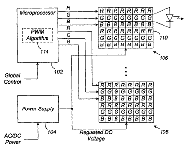
A typical LED based lighting system employs at least three different colors of LEDs, for example, red (R), green (G), and blue (B), arranged in a repeating array. The colors can be combined in different proportions to produce thousands of resultant colors (e.g., white) when viewed by the human eye. FIG. 1 shows a general layout of a portion of a basic LED based lighting system 100. The system 100 has a microprocessor 102, a power supply 104, and one or more arrays of LEDs 106, 108. Each array 106, 108 includes a number of red, green, and blue LEDs, one of which is shown at 110. Within each array, LEDs that emit the same color have their cathode and anodes electrically tied together to form a channel. Each channel is controlled by the microprocessor 102 independently of the other channels, both within a given array and also from array to array in some cases.
Although only one microprocessor 102 is shown, most applications will have multiple microprocessors 102 controlling multiple sets of LED arrays 106, 108. It is also possible to have one microprocessor controlling a single LED array. In a typical installation, one microprocessor controls one light fixture, which can include several LED arrays. Additionally, although the arrays 106, 108 show an equal number of red, green, and blue LEDs, in some applications, there may be more or fewer of one color than others. Moreover, some arrays may have a higher or lower total number of LEDs than others. It is also possible to have an array with only one LED for each of the constituent colors.
In operation, a user selects the resultant light output (e.g., white) for the desired LED arrays 106, 108 via a global control unit (not expressly shown). The global control unit then relays the desired resultant color to the appropriate microprocessors 102. Each microprocessor 102 controls the relative intensity level of the channels within its set of arrays to achieve the desired resultant color. The intensity level of a channel is controlled using pulse-width modulation (PWM) of a fixed current source (e.g., 20 mA, 40 mA, etc.) provided by the power supply 104. The power supply 104 is connected to the LED arrays 106, 108 via a plurality of switches (not expressly shown) in either a common anode or a common cathode configuration. Each microprocessor 102 then modulates the current for its LED channels by turning on and off the appropriate switches, which may be any suitable switching device (e.g., a field effect transistor (FET)).
Within each microprocessor 102, a PWM algorithm 114 adjusts the PWM for each channel to achieve the desired resultant color. PWM allows linear control of the intensity level of the LEDs; that is, the intensity level of an LED is directly proportional to the width of the pulse. The algorithm 114 uses pre-stored calibration data to determine the PWM that should be applied to each channel to achieve the resultant color. By varying the PWM of the different channels, it is possible to generate thousands of different resultant colors.
Successful execution of the above LED based lighting system 100 requires that the individual LEDs 110 within a channel of a given array be closely matched in intensity (brightness) and wavelength (color.) Ideally, every LED of a particular color would have the same intensity and wavelength. In reality, the LED manufacturing process is not perfect, and manufacturers have to bin (sort) the LEDs by intensity and wavelength. For an LED of a given color, it is common to have six or more different bins. Thus, an array with three different colors could theoretically require up to 216 different bins to cover all the possible combinations.
The logistics of managing so many bins is both complex and expensive. A more economic solution is to closely match the intensity and wavelength of LEDs of a given color on a single array, but permit variation from array to array. A calibration process can then be used to normalize the resultant output on an array by array basis so that multiple arrays produce substantially the same color when governed by a global command. The calibration process generates the maximum possible intensity at a specific color target. The color target is identified using the CIE (Commission International de l'Eclairage) chromaticity coordinates u' and v'. The coordinates for "High White," for example, are u'=0.2221 and v'=0.5024. Any combination of red, blue, and green that results in these coordinates will produce a High White color. The PWM for each channel that generates the maximum intensity level at the target color is then stored in the microprocessor.
Unfortunately, the intensity level of an LED changes with temperature, which can cause a drift in the LED's color. And while the human eye is relatively insensitive to variations in the intensity (brightness) of a given color, it is very sensitive to variations in the color (wavelength) itself A shift of 3-4 nanometers in the wavelength of a LED creates a color shift that is noticeable to the human eye. Since the resultant color generated by the lighting system is composed of three or more colors, a minor shift in output of any one of the component colors may lead to visible color shifts. The charts in FIGS. 2A-2B show examples of bow the u' and v' parameters can change with temperature. As the temperature of the LED rises, its output drops, which changes the u' and v' parameters. This intensity drop varies for each LED color, since the different colors are based on different LED technologies.
In typical installations, the LED arrays for the same microprocessor and/or different microprocessors are placed in different locations and may be exposed to different thermal environments. For example, in airplane cabin lighting systems, one array or set of arrays may be installed under an air conditioning vent while a second array or set of arrays is installed in a warmer spot. Since the LEDs at the different locations now operate at different temperatures relative to each other, the resultant color produced at those locations will be different relative to each other. If the difference in temperature is large enough, there will be a significant variation in output color between the locations.
Accordingly, what is needed is a way to compensate for thermal differences in LED based lighting systems. More specifically, what is needed is a way to adjust the PWM of the LEDs to compensate for differences in the temperature of the operating environment.
Brief summary of the invention
The present invention is directed to a method and system for compensating for color variations due to thermal differences in LED based lighting systems. The method and system of the invention characterizes the LEDs to determine what PWM is needed at various operating temperatures to achieve a desired resultant color. The characterization data is then stored in the microprocessor either in the form of a correction factor or as actual data. When an operating temperature that is different from a calibration temperature is detected, the characterization data is used to adjust the PWM of the LEDs to restore the LEDs to the desired resultant color.
In general, in one aspect, the invention is directed to a method of compensating for color variation due to temperature change in an LED based lighting system that has at least one LED array, wherein same color LEDs are electrically connected to form LED channels. The method comprises determining a pulse width needed for at least one LED channel to achieve a predetermined target color at at least a first and a second temperature, calculating a pulse width correction factor for the at least one LED channel based on the pulse width needed to achieve the predetermined target color at the at least first and second temperatures, and correcting the pulse width for the at least one LED channel using the pulse width correction factor to achieve the predetermined target color.
In general, in another aspect, the invention is directed to an LED based lighting system with thermal compensation capability. The system comprises at least one LED array having same color LEDs electrically connected to form LED channels, a microprocessor connected to and independently controlling each LED channel of the LED array to achieve a desired resultant color, and a temperature sensor connected to the microprocessor for detecting an operating temperature of the at least one LED array. An algorithm stored on the microprocessor is configured to cause the microprocessor to compensate for differences in the operating temperature of the at least one LED array.
In general, in yet another aspect, the invention is directed to a method of compensating for color variation due to temperature change in an LED based lighting system that has at least one LED array, wherein same color LEDs are electrically connected to form LED channels. The method comprises deriving a temperature compensation curve for the LED array, calculating a correction factor for at least one LED channel based on temperature compensation curve, and compensating for differences in an operating temperature for the LED array.
In general, in still another aspect, the invention is directed to a method of calibrating an LED based lighting system that has at least one LED array, wherein same color LEDs are electrically connected to form LED channels. The method comprises the steps of stabilizing the LED channels, maximizing an intensity level of one of the LED channels, and adjusting an intensity level of at least one other LED channel until a predetermined target color is achieved. The method further includes the step of repeating the above steps after a predetermined amount of time.
Claims
1. A method of compensating for color variation due to temperature change in an LED based lighting system having at least one LED array, wherein same color LEDs are electrically connected to form LED channels, the method comprising: determining a pulse width needed for at least one LED channel to achieve a predetermined target color at at least a first and a second temperature; calculating a pulse width correction factor for the at least one LED channel based on the pulse width needed to achieve the predetermined target color at the at least first and second temperatures; correcting the pulse width for the at least one LED channel using the pulse width correction factor to achieve the predetermined target color.
2. The method according to claim 1, wherein the pulse width correction factor is calculated for every LED array in the LED based lighting system.
3. The method according to claim 1, wherein the pulse width correction factor is calculated for some of the LED arrays in the LED based lighting system and then applied to other LED arrays in the LED based lighting system.
4. The method according to claim 1, further comprising calibrating the LED channels, including (a) maximizing an intensity level of one of the LED channels, and (b) adjusting an intensity level of at least one other LED channel until the predetermined target color is achieved.
5. The method according to claim 4, wherein the calibrating step further includes repeating steps (a) and (b) after a predetermined amount of time.
6. The method according to claim 1, wherein the first operating temperature is a calibration temperature.
7. The method according to claim 6, wherein the second operating temperature is less than the first operating temperature.
8. The method according to claim 6, wherein the second operating temperature is greater than the first operating temperature.
9. The method according to claim 4, further comprising detecting an operating temperature of the at least one LED array, wherein the step of correcting is performed only if a difference between the calibration temperature and the operating temperature is above a predefined threshold value.
10. The method according to claim 1, wherein the target color is defined by chromaticity coordinates.
11. An LED based lighting system with thermal compensation capability, comprising: at least one LED array having same color LEDs electrically connected to form LED channels; a microprocessor connected to and independently controlling each LED channel of the LED array to achieve a desired resultant color; a temperature sensor connected to the microprocessor for detecting an operating temperature of the at least one LED array; and an algorithm stored on the microprocessor and configured to cause the microprocessor to compensate for differences in the operating temperature of the at least one LED array.
12. The system of claim 11, wherein the algorithm causes microprocessor to compensate for differences in an operating temperature of the at least one LED array by causing the microprocessor to: receive the desired resultant color; apply pulse-width modulation to each LED channel, the pulse-width modulation having a pulse width calibrated to achieve to the resultant color; monitor an operating temperature for the at least one LED array; calculate a temperature difference between the operating temperature and a calibration temperature; and adjust the pulse width of the pulse-width modulation for at least one LED channel based on the temperature difference.
13. The system of claim 12, wherein the algorithm is further configured to cause the microprocessor to wait a predetermined amount of time for the LED array to stabilize before detecting an operating temperature.
14. The system of claim 11, wherein the temperature sensor is an on-board temperature sensor that is built into the microprocessor.
15. The system of claim 11, wherein the LED arrays are installed as a transportation cabin lighting system.
16. The system of claim 12, wherein the microprocessor adjusts the pulse width of the pulse-width modulation using a correction factor for each LED channel.
17. The system of claim 16, wherein the correction factor for each LED channel is calculated from actual data measured for the LED channel.
18. The system of claim 16, wherein the correction factor for each LED channel is estimated from data measured for one or more other LED channels.
19. The system of claim 12, wherein the microprocessor adjusts the pulse width of the pulse-width modulation using a look-up table.
20. A method of compensating for color variation due to temperature change in an LED based lighting system having at least one LED array, wherein same color LEDs are electrically connected to form LED channels, the method comprising: deriving a temperature compensation curve for the LED array; calculating a correction factor for at least one LED channel based on temperature compensation curve; and compensating for differences in an operating temperature for the LED array.
21. The method of claim 20, wherein the step of compensating includes correcting a pulse width for the at least one LED channel using the correction factor.
22. The method according to claim 20, wherein the compensation curve is a pulse width versus temperature curve, further comprising determining the slope of the pulse width versus temperature curve.
23. The method according to claim 22, wherein the slope of the pulse width versus temperature curve is determined by averaging data from a predetermined number of LED channels.
24. The method according to claim 22, wherein the pulse width versus temperature curve is determined based on at least two data points.
25. The method according to claim 20, wherein the step of compensation is performed only if a difference between an operating temperature and a calibration temperature is above a predefined threshold value.
26. A method of calibrating an LED based lighting system having at least one LED array, wherein same color LEDs are electrically connected to form LED channels, the method comprising: (a) stabilizing the LED channels; (b) maximizing an intensity level of one of the LED channels; (c) adjusting an intensity level of at least one other LED channel until a predetermined target color is achieved; (d) waiting a predetermined amount of time; (e) readjusting the intensity level of the at least one other LED channel until the predetermined target color is achieved again; and (f) storing the intensity levels of the LED channels as calibration intensity levels.
27. The method according to claim 26, further comprising measuring an operating temperature of the LED channels after step (f) and using the measured operating temperature as a calibration temperature.
28. The method according to claim 27, further comprising repeating steps (d)-(f) until a difference in calibration temperature between a current iteration and a previous iteration is below a predetermined threshold.
29. The method according to claim 26, further comprising calculating a pulse width correction factor for the LED channels using the stored calibration intensity levels.
See full document in pdf.
