Discomfort Caused by Glare from Luminaires with a Non-Uniform Source Luminance
Glare and the resulting discomfort are a persistent issue in lighting that became even bigger with the introduction with LEDs as a light source. While the UGR method is well established, it is sometimes heavily discussed if it is appropriate for SSL. The limitations of the UGR method need to be understood. Peter Thorns BSc(Hons), CEng, FCIBSE, FSLL, explains these limitations and consequently describes the research and how to apply correction measures.
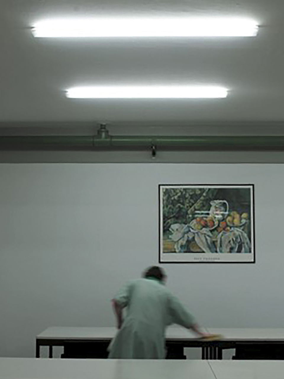
The Unified Glare Rating (UGR) methodology for calculating indoor discomfort glare, as given in CIE 1995 [1] and CIE 2010 [2] is well established and used internationally in many standards and codes of practice. It allows us to evaluate the perceived discomfort glare from lighting installations such as that shown in figure 1. The standard formula is shown in Equation 1 below.
 (EQ 1)
where the summation is over all sources in the field of view and where ...
RUG is the UGR value
Ls is the source luminance in the direction of the observer
ω is the solid angle subtended by the source at the observer's eye
p is the position index, which depends on the angular position of the source
in the observer's field of view
Lb is the general field luminance controlling the adaptation level of the
observer's eye, or background luminance
 Figure 1: Example lighting installation with poor glare control
About the Limitations of the UGR Method
The UGR methodology has acknowledged limitations. It is limited to light sources which have a maximum subtense at the eye of between 0,0003 sr and 0,1 sr. It also uses defined limiting criteria that relate to an observer positioned against the wall of a rectangular room looking in a specific direction, as opposed to sitting at a desk in a specific location within the room. However, as a pragmatic solution that has been shown to work in the majority of situations over time the value of the methodology has been demonstrated.
(For small or large light sources outside the limits of applicability for UGR, alternative methods are available in CIE 2002 [3]).
However, a further limitation of the UGR methodology is that light sources should be uniform in luminance. Research has indicated that luminaires with large luminance variation, the UGR formula does not correctly predict the perceived discomfort glare. Waters et al. [4] concluded that non-uniform glare stimuli could cause more glare perception than uniform stimuli when viewed directly, but that the glare perception was nearly the same in peripheral vision. Takahashi et al. [5] reached the same conclusion and added the observation that a glare source with a matrix arrangement has a higher position index than a uniform glare source. Tashiro et al. [6] concluded that the discomfort glare from non-uniform light sources is larger than that of uniform light sources when the illuminance at the observer's eye remains the same.
The results of one research paper from Hara et al. [8] are shown graphically in Figure 2 below and clearly show the change in perceived discomfort glare between a uniform and a non-uniform stimulus.
 Figure 2: Difference in UGR (DUGR) between a non-uniform and a uniform glare source according to Hara et al. [8] (Source: CIE 2019 [7])
Research on Corrections of the UGR Formula
Many researchers have proposed corrections to the UGR formula to account for this, however with little consensus of a single unified solution. The corrections are generally based on adjustments of the position index, the average source luminance or the solid angle for the luminous area.
In response to this issue the CIE set up a joint technical committee, with experts from Division 1 (Vision and Colour) and Division 3 (Interior Environment and Lighting Design), with terms of reference to review the literature on glare from non-uniform sources, identify the parameters that influence the discomfort prediction, define limits to the applicability of the UGR formula, propose a correction to the UGR formula to account for non-uniform glare sources.
The result is the technical report CIE 232:2019 Discomfort Caused by Glare from Luminaires with a Non-Uniform Source Luminance [7], a report that describes a method to adjust the UGR formula to account for non-uniform light source.
Parameters were identified that influence the discomfort prediction, which can be split into either observer related parameters or luminance pattern related parameters. Observer related parameters include the position of the source in the field of view, viewing distance, background luminance and type of task. Luminance pattern related parameters are shown in Figure 3 below.
 Figure 3: Luminance pattern related parameters that influence glare perception (source CIE 2019 [7])
Research Results and Correction Methods for the UGR Formula
As research demonstrates that the lower the uniformity, the higher the perceived discomfort glare, the effects of luminance pattern related parameters on uniformity may be summarised as uniformity decreases when
• there is a smaller area ratio between LED and the rest of the glare
source (e.g. smaller LED size, less LED per area and steeper
luminance gradients);
• there is a higher luminance of LED inside the luminaire;
• there is a higher luminance ratio between the LED and
immediate surrounding.
All of the differing approaches to modifying the existing UGR formula may be summed up by writing the formula as
 (EQ 2)
where is the corrected UGR value, , and k is a uniformity correction factor. k is based upon both the effective source area and the effective source luminance.
Alternatively, for a single glare source Equation (2) may be written in terms of Equation (1):
![]() (EQ3)
(EQ3)
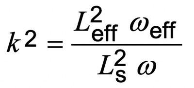
The method given to calculate a value for k is via the use of luminance images. The luminance image is used to calculate the effective solid angle of the luminous area and the effective luminance. From these values k may be calculated using Equation (4).
 (EQ 4)
where
Leff is the effective luminance
ωeff is the effective solid angle of the luminous area
Ls is the average source luminance as defined in CIE 1995 [1]
ω is the solid angle of the source luminance as defined in CIE 1995 [1]
(Note: by applying this new source area definition, the UGR as laid out in CIE 1995 and CIE 2010 may be applied without correction as k=1, i.e. 〖R'〗_UG=R_UG).
The luminance image may be processed in a number of ways.
These are:
EA: The effective area method, based upon a luminance threshold
EL-std: The effective luminance method, based upon the standard
deviation of pixel values
EL-geom: The effective luminance method based upon the geometric mean
of pixel values
The method chosen for the correction factor shown in Equation (4 was EL-geom, based upon an analysis of how the three potential methods correctly predicted the results from a number of research studies. The results from one of these studies is shown in Figure 4.
 Figure 4: The difference in UGR (DUGR) between a non-uniform and a uniform glare source (experimental data of Utsunomiya University)(Source: CIE 2019 [7])
The practical implication of this is that as the non-uniformity of the glare source increases (i.e. the numerator in Equation (4) increases with respect to the denominator), the perceived discomfort glare will also increase because it is additive, as shown in Equation (3). Representative values of 8 log(k²), and hence the increase in UGR value, are shown in Figure 5 for k = 1 to k = 3.
 Figure 5: Values of 8 log(k²) for values of k
Conclusions
In conclusion the publication CIE 232:2019 [7] provides a verified method to predict perceived discomfort glare from non-uniform light sources, overcoming the current issue of UGR values predicting lower discomfort glare than that perceived in practice from non-uniform light sources. It should therefore be used in practice to allow the design of better and more comfortable work spaces.
Remark:
This and other CIE publications are available for purchase from the CIE Webshop. Members of CIE National Committees are eligible for a 66.7 % discount on the advertised price.
References:
[1] CIE 117:1995. Discomfort Glare in Interior Lighting. CIE, Vienna.
[2] CIE 190:2010. Calculation and Presentation of Unified Glare Rating Tables
for Indoor Lighting Luminaires. CIE, Vienna.
[3] CIE 147:2002. Glare from Small, Large and Complex Sources. CIE, Vienna.
[4] Waters CE, Mistrick RG, Bernecker CA. "Discomfort glare from sources
of non-uniform illuminance". Journal of the IES 1995: 24: 73-85.
[5] Takahashi H, Kobayashi Y, Onda S, Arikura T. "Position index for the matrix
light source". Journal of Light and Visual Environment 2007: 31: 128-133.
[6] Tashiro T, Kawanobe S, Kimura-Minoda T, Kohko S, Ishikawa T, Ayama M.
"Discomfort glare for white LED light sources with different spatial
arrangements". Lighting Research and Technology 2015: 47: 316-337.
[7] CIE 232:2019. Discomfort Caused by Glare from Luminaires with a
Non-Uniform Source Luminance. CIE, Vienna.
[8] Hara N, Hasegawa S. "Study on Discomfort Glare Rating on the Luminaire
with LED Array". Journal of Illuminating Engineering Institute of Japan 2012:
96(2):81-88.

